Transcription of DLAB - A DOWNSCALED DISTRIBUTION LABORATORY …
1 dlab - A DOWNSCALED DISTRIBUTION LABORATORY FOR education AND RESEARCH ON intermittent EARTH FAULTS Dahlquist J., J nsson A., rndal C. and Akke M. IEA, Lund University ABSTRACT This paper presents a general overview of dlab , which is a DISTRIBUTION LABORATORY for education and research on resonance grounded DISTRIBUTION networks. Specifically, the paper shows how intermittent earth faults have been implemented in the LABORATORY . The experimental platform can now be used to develop and evaluate different methods for indication of intermittent earth faults. For some years, Eln t (hereafter referred to as in the text) has sponsored LTH to build up a DOWNSCALED DISTRIBUTION LABORATORY abbreviated dlab . The idea is to promote education on resonance grounded DISTRIBUTION networks and research on current topics such as intermittent earth faults.
2 The increased use of cables in Swedish DISTRIBUTION networks, results in earth faults with different characteristic compared to overhead lines. In cabled networks, intermittent faults and also evolving faults have been recorded with a high-end fault recorder. These disturbance recordings reveal that intermittent faults have a high frequency content well above the fundamental frequency. Traditional line models, consisting of one pi-link only, seem to be insufficient to reproduce the high frequency content found in real disturbance recordings. Therefore an effort has been made to make a new cable models with improved high frequency behavior, which expands the valid frequency range from 50 Hz up to some kHz. The first step was to make a theoretical reference model based on transmission line model with distributed parameters.
3 In addition the skin-effect has been included in the reference model. The physical implementation has been made with several pi-links where the component values have been chosen to replicate the reference model s frequency response. The intermittent switching is implemented by a semi-conductor relay with instantaneous on-switch on and with off-switch at the first zero crossing of the current. The relay is software controlled which makes it possible to control several switching parameters to fabricate different type of intermittent faults. The paper compares recordings of intermittent earth faults in dlab with real disturbance recordings from a 20 kV transformer station in southern Sweden. INTRODUCTION Background is one of the major players in Swedish power DISTRIBUTION . In the current situation, E. ON is responsible for DISTRIBUTION of electricity to approximately one million end customers and sales of around EUR 630 million.
4 In recent years, powerful storms such as Gudrun and Per hit Sweden. They caused extensive damage to the power grid and resulted in many customers were without electricity. The results of the storms in combination with increased regulatory requirements for uninterrupted power supply, led to start the project Krafttag which aimed to weather secure much of the overhead lines in risk areas. has in recent years improved the reliability of medium voltage networks by extensive cablification. New problems not previously on the daily agenda have emerged due to increased usage of cables. One of these problems is that underground cables compared to overhead power line, causing a higher capacitive current, which in case of an earth fault results in large fault currents. Certain types of faults, such as bad cable joints or cracks in the insulators, might cause a sequence of extinguishments and re-ignitions of the earth fault.
5 This is called intermittent ground faults and usually contains a high proportion of transients. To put focus on the new problems with increased cablification, the project dlab was started 2008 at the Department of Industrial Electrical Engineering and Automation (IEA), Lund University, Sweden. Objectives Earth fault protection units are usually made to measure the fundamental frequency and may have trouble to function correctly at intermittent ground faults. One example is directional earth fault protection based on active zero sequence current, which in some cases fails to operate. This might lead to unselective backup tripping from neutral point voltage protection, which unnecessarily disconnects all feeders in the station. The dlab research project aims to increase the understanding of intermittent earth faults and the effect on earth fault protection.
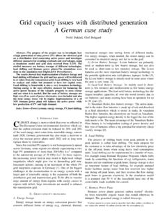
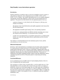
6 Work is made in dlab to implement models for intermittent faults, which should be used to reproduce and explain erroneous protection functions. dlab A downsized LABORATORY for DISTRIBUTION networks was initiated in 2008. The aim was, and still is, to provide a good platform for teaching and research on resonance earthed MV networks. dlab is a research group within Lund University and is sponsored by The name dlab is an abbreviation of DISTRIBUTION LABORATORY . An additional goal is to offer an educational LABORATORY exercise for students as well as the power industry. Picture 1: LABORATORY setup. LABORATORY setup Within dlab a low voltage model of a MV DISTRIBUTION network has been created. The model includes underground cables, overhead lines, protection units, neutral point resistance, a Petersen coil with automatic tuning based on either network un-symmetry, or current injection.
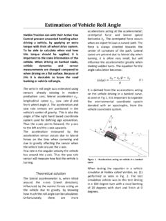
7 There is a possibility to apply permanent earth fault with different fault resistance, but also short duration intermittent earth faults. The model properties have been compared against both field tests and simulation results, and agrees reasonable well. The single line diagram is illustrated in Figure 1. Figure 1: Single line diagram. Conversion between MV- network and dlab Because experiments on MV level can be difficult and dangerous, dlab has been scaled down to a lower voltage. With regulatory requirements and the possibility to use small components, dlab is designed for 220 V and 5 A. To relate dlab results to the real MV grid, conversion factors have been calculated. The conversion factors in Table 1, are given for a 24 kV network with a base current of 50 A. dlab EON Conversion Factor Voltage, Phase 3240 V 324 kV 100 Base Current 5 A 50 A 10 Base Impedance 277 10 Table 1: Conversion factor between dlab and 24 kV network The resulting conversion factors for capacitance and inductance are and 10, respectively.
8 intermittent EARTH FAULTS The increased use of buried cables in the MV network has led to more intermittent earth faults. As the characteristics of such faults differ from permanent faults, it adds new demands on the earth fault protection scheme. Classification of intermittent earth faults An intermittent earth fault is characterized by its short duration and that its repetitive behavior, which can be nearly periodic. The arc ignites when the voltage at the fault location exceed the break down voltage, and self-extinguish at some zero current crossing, only to arc again when voltage over the fault is increased. Real field measurements Two different field measurements have been done in the dlab project. The procedure to fabricate the faults have been slight different: Test 1 was performed with a short cable (10m) connected to a not used feeder in a network station.
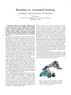
9 The cabled where prepared by drilling a hole through the insulation down to the conductor, pouring water in to the hole, putting one shield wire close to the hole and at last energize the cable for about 1 second. Picture 2a & 2b: intermittent fault by drilling hole and pouring water method Test 2 was performed with two conductors with a small air gap in between. One conductor where connected to earth and the other to one of the phases. By slowly decreasing the gap between the conductors arcs starts to emerge. Picture 3: intermittent fault by decreasing air gap method Recordings The recordings presented are taken from the first field-test due to better measurement quality. The equipment used was from National Instruments and had a sampling rate of 50 kHz, with a specified effective bandwidth of about 23 kHz.
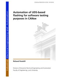
10 Figure 2: Zero sequence current in feeders at intermittent earth fault Figure 2 includes an example of the current spikes that could occur during intermittent faults. It is shown that the whole sequence is taking a fraction of a millisecond. This indicates that high sampling rates is essential for protection unit aiming for this fault type. Frequency content in measurements The measurement clearly shows that intermittent faults contain high frequency components, well above the fundamental 50 Hz signal. When examining the current there are clear spikes in the measurement files. The rise time of these spikes imply that the fault transients also contain higher frequency components with very short time duration. Another way is to calculate the frequency content by using FFT, but the result is highly dependent on selected time window length and possible averaging, which makes it hard to draw far-reaching conclusions.