Transcription of DNR Duct Smoke Detector - System Sensor
1 DNR Duct Smoke DetectorINSTALLATION AND MAINTENANCE INSTRUCTIONS 3825 Ohio Avenue, St. Charles, Illinois 601741-800-SENSOR2, FAX: of Contents Page[1] Limitations of Duct Smoke Detectors ..1[2] General Description ..1[3] Contents of the Duct Smoke Detector Kit ..1[4] Detector Installation ..1[5] Sampling Tube Installation ..2[6] Measurement Tests ..3[7] Field Wiring ..4[8] Verification of Operation ..4[9] Dectector Cleaning Procedures ..5[10] Sensor Replacement ..5[11] Optional Accessories ..5 Warranty ..6 BEFORE INSTALLINGRead System Sensor s Applications Guide for Duct Smoke Detectors (HVAG53), which provides detailed information on Detector spacing, placement, zoning, wiring, and special applications. This manual is available online at NFPA Standards 72 and 90A should also be referenced for detailed information. NOTICE: This manual shall be left with the owner/user of this : This Detector must be testeds and maintained regularly follow-ing NFPA 72 requirements.
2 The Detector must be tested an maintained regularly following NFPA 72 requirements. According to NFPA, the Detector should be visually inspected semiannually and functionally tested at least once a year. This may need to be more frequent depending on the air quality of the duct supply air.[1] LIMITATIONS OF DUCT Smoke DETECTORS WARNINGThe National Fire Protection Association has established that DUCT DETEC-TORS MUST NOT BE USED AS A SUBSTITUTE FOR OPEN AREA Detector PROTECTION as a means of providing life safety. Nor are they a substitute for early warning in a building s regular fire detection Sensor supports this position and strongly recommends that the user read NFPA Standards 90A, 72, and 101. The DNR Air Duct Smoke Detectors are listed per UL device will not operate without electrical power. Fire situations may cause an interruption of power. The System safeguards should be discussed with your local fire protection device will not sense Smoke unless the ventilation System is operating and the cover is this Detector to function properly, it MUST be installed according to the instructions in this manual.
3 Furthermore, the Detector MUST be operated within ALL electrical and environmental specifications listed in this manual and the Sensor head installation manual. Failure to comply with these requirements may prevent the Detector from activating when Smoke is present in the air duct.[2] GENERAL DESCRIPTIONS moke introduced into this air duct System will be distributed throughout the entire building. Smoke detectors designed for use in air duct systems are used to sense the presence of Smoke in the duct. Model DNR Air Duct Smoke Detector utilizes photoelectric technology for the detection of Smoke . This detection method, when combined with an efficient housing design, samples air passing through the duct and allows detection of a developing hazardous condition. When sufficient Smoke is sensed, an alarm signal is initiated at the fire control panel monitoring the Detector , and appro-priate action can be taken to shut off fans, blowers, change over air handling systems, etc.
4 These actions can facilitate the management of toxic Smoke and fire gases throughout the areas served by the duct DNR incorporates a Sensor cover tamper feature that provides a trouble signal at the panel immediately if the cover is removed or improperly in-stalled. Proper installation of the Sensor cover removes the trouble programmed with the System control panel, two LEDs on each duct Smoke Detector light to provide local visible indication. The DNR provides a remote alarm output for use with auxiliary devices, such as the RA100Z remote LED annunciator, as well as remote test capability with the RTS451/RTS151 or RTS451 KEY/RTS151 KEY Remote Test Stations.[ ] Detector FEATURE SET Utilizes plug-in head Sampling tubes install from front and rear Compatible with existing accessories Able to address Detector per code switches on Sensor head.[3] CONTENTS OF THE DUCT Smoke Detector KIT1. Sensor /power side and covers (use appropriate Sensor per the System control panel)2.
5 Three #10 sheet metal screws for mounting3. Drilling template4. One sampling tube end cap5. One plastic exhaust tubeNOTE: A DST sampling tube must be ordered to complete the installation. It must be the correct length for the width of the duct where it will be installed. See Table 1 on page 3 to determine the inlet tube required for different duct widths. [4] Detector INSTALLATION [ ] VERIFY DUCT AIR FLOW DIRECTION AND VELOCITYM odel DNR detectors are designed to be used in air handling systems having air velocities of 100 to 4000 feet per minute. Duct widths from 6 inches to 12 feet can be accommodated. Be sure to check engineering specifications to ensure that the air velocity in the duct falls within these parameters. If neces-sary, use a velocity meter (anemometer) to check the air velocity in the Operating Temperature: 4 to 158 F ( 20 to 70 C); 32 F to 120 F (0 C to 49 C) with module installed in the DNRS torage Temperature: 22 to 158 F ( 30 to 70 C)Humidity: 0% to 93% Relative Humidity Non-condensingAir Velocity: 100 to 4000 ( to m/sec.)
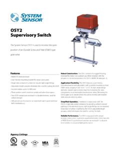
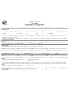
6 Rectangular Footprint Dimensions: in L 5 in W in D (37 cm L cm W cm D)Square Footprint Dimensions: in L 9 in W in D ( cm L cm W cm D)Weight: pounds; kgElectrical (See applicable Detector head installation manual for electrical specifications. Use the Base/ Sensor Cross Reference chart at http:\\ to determine applicable Sensor head.)ACCESSORY CURRENT LOADS AT 24 VDCDEVICESTANDBYALARMRA100Z0mA12mA Max. 1 I56-3051-011R 06-10 EXHAUST TUBESENSOR HEADSENSOR MODULE COVERWIRING COMPARTMENT COVERWIRING COMPARTMENTSENSOR MODULESAMPLING TUBENOTE: Sensor HEAD IS ONLY INCLUDED ON SPECIFIED SEPERATELY[ ] DETERMINE MOUNTING LOCATION AND CONFIGURATIONOn ducts wider than 18 inches it is recommended that the Detector be mounted downstream of a bend, obstruction in the duct, or the supply or return air inlet.
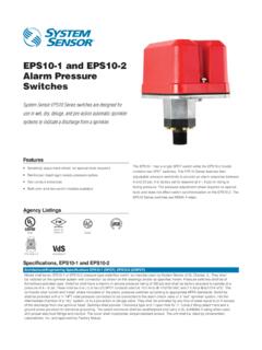
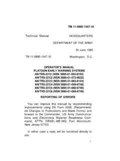
7 Exception: Installation of duct detectors can be on or within a commercial packaged rooftop heating and air-conditioning System , fire/ Smoke dampers and economizers. They may be mounted in either the supply and/or return air section as determined by local a suitable location is selected, determine if the Detector is to be mounted in a side-by-side rectangular configuration or a top-over-bottom square configuration as shown in Figure 2. If mounting in the square configuration, remove the rear attachment screw, rotate the unit at hinge, and replace the screw into the new attachment hole as shown in Figure 2. Do NOT remove the hinge screw during this process. Final installation approval shall be based upon passing differential pressure and Smoke entry tests described in the Measurement Tests 2:REMOVE SCREW AND PIVOTDETECTOR AS SHOWN SCREWTO SECURE DETECTORIN [ ] DRILL THE MOUNTING HOLESR emove the paper backing from the mounting template supplied.
8 Affix the template to the duct at the desired mounting location. Make sure the template lies flat and smooth on the duct. [ ] FOR RECTANGULAR SIDE-BY-SIDE MOUNTING CONFIGURATION:Center punch at (4) target centers: (2) A for sampling tubes and (2) B for the rectangular configuration mounting tabs as shown on mounting template. Drill pilot holes at target A centers and cut two inch diameter holes using a 13 8-inch hole saw or punch. Drill .156 inch diameter holes using a 5 32 inch drill at target B centers.[ ] FOR SQUARE TOP-OVER-BOTTOM MOUNTING CONFIGURATION:Center punch at (4) target centers: (2) A for sampling tubes and (2) C for the square configuration mounting tabs as shown on mounting template. Drill pilot holes at target A centers and cut two inch diameter holes using a 13 8-inch hole saw or punch. Drill .156 inch diameter holes using a 5 32 inch drill at target C centers. If desired, drill an additional .156 inch hole at the location of one of the mounting tabs on the lower housing.
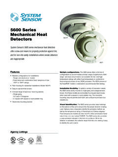
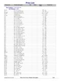
9 [ ] SECURE THE DUCT Detector TO THE DUCTUse two (rectangular configuration) or three (square configuration) of the pro-vided sheet metal screws to screw the duct Detector to the : Do not overtighten the screws.[5] SAMPLING TUBE INSTALLATION [ ] SAMPLING TUBE SELECTIONThe sampling tube must be purchased separately. Order the correct length, as specified in Table 1, for width of the duct where it will be installed. The sampling tube length must extend at least 2/3 across the duct width for optimal sampling tube is always installed with the air inlet holes facing into the air flow. To assist proper installation, the tube s connector is marked with an arrow. Make sure the sampling tube is mounted so that the arrow points into the airflow as shown in Figure 3. Mounting the Detector housing in a vertical orientation is acceptable provided that the air flows directly into the sam-pling tube holes as indicated in Figure 3. The sampling tube and exhaust tube can be mounted in either housing connection as long as the exhaust tube is mounted downstream from the sampling 1.
10 EXPLODED VIEW OF DUCT Smoke Detector COMPONENTS:H0569-06 2 I56-3051-011R 06-10 FIGURE HOLE12 1/4 2 NOTE: Air currents inside the duct may cause excessive vibration, especially when the longer sampling tubes are used. In these cases, a 3 inch floor flange (available at most plumbing supply stores) may be used to fasten the sam-pling tube to the other side of the duct. When using the flange/connector mounting technique, drill a 1 to 1 inch hole where the flange will be used[ ] MODIFICATIONS OF SAMPLING TUBEST here may be applications where duct widths are not what is specified for the installation. In such cases, it is permissible to modify a sampling tube that is longer than necessary to span the duct a diameter (#10) drill and add the appropriate number of holes so that the total number of holes exposed to the air flow in the duct is 10 to 12.