Transcription of Doherty Power Amplifier Based on the Class-F …
1 Doherty Power Amplifier Based on the Class-F Load Network Minwoo Cho1, 1, Mincheol Seo1, Hyungchul Kim1, Inoh Jung1, Hwiseob Lee1, Cheonseok Park1 and Youngoo Yang1 Sungkyunkwan University, 300 Cheoncheon-dong, Jangan-gu, Suwon, Gyeonggi-do, 440-476 Korea {hellocmw, starsorf, gudurial, junginoh11, Abstract. This paper presents a Doherty Amplifier with improved efficiency Based on the Class-F load network for both carrier and peaking amplifiers. The peaking Amplifier is designed to have normal Class-F operation with the 2nd and 3rd harmonic-tuned load network. For better linearity, the carrier Amplifier has a class -AB bias point and an identical Class-F load network with the peaking Amplifier . The proposed Doherty Amplifier was designed and implemented for LTE applications at the 751 MHz band.}
2 For CW excitation, the implemented Amplifier has a gain of dB and a PAE of % at an output Power of dBm. For two-tone signal excitation, an IMD3 of -30 dBc was observed at an output Power of dBm. Using an LTE signal Based on 16-QAM, the proposed Power Amplifier exhibited a PAE of %, an ACLR of dBc at an offset of 5 MHz, and an EVM of % at a back-off level of dB. Keywords: Doherty Amplifier , Class-F Amplifier , harmonic-tuned load network, long-term evolution (LTE). 1 Introduction For wireless communication systems, Power Amplifier is the most important part for determining efficiency of the system. Many techniques have been come out to improve efficiency of the Power Amplifier . There are high-efficiency switching-mode Power amplifiers, such as class -D and E, and harmonic-controlled amplifiers, such as Class-F and inverse Class-F [1]-[6].
3 Especially, Class-F Amplifier has very simple structure and high-efficiency characteristics at high frequency region, so that it is suitable for modern wireless communication systems [7], [8]. This research was suppoerted by Basic Science Research Program through the Nationanl Research Foundation of Korea (NRF) funded by the Ministry of Education Science and Technology(NRF-2011-220-D00084). The corresponding author. 15In addition to efficiency at the peak signal, another very important aspect for the Power Amplifier is its efficiency at low and mid Power range because of high peak-to-average Power ratio (PAPR) of the signal. For high efficiency at low or mid Power level, Doherty Amplifier and some bias modulation techniques, such as envelope elimination and restoration (EER) and envelope tracking (ET), have been used [9]-[15].
4 Among them, Doherty Amplifier has comparably high efficiency and low complexity to others. In this paper, we adopt the Class-F load network for both carrier and peaking amplifiers in the Doherty Amplifier . By applying a class -AB bias to the carrier Amplifier , the overall linearity is not degraded, while significant improvement in efficiency can be observed due to the harmonic tuning using Class-F load network. The proposed Doherty Amplifier was designed and implemented using Gallium-Nitride high electron mobility transistor (GaN HEMT) for long term evolution (LTE) applications at the 751 MHz band. Simulated and measured performances will be provided. 2 Class-F Amplifier design /19 /12 Fundamental MatchingSecondHarmoniccontrolThirdHarmon iccontrol /4 /8 /16 /18 Fig.
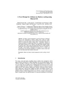
5 1. Load network for the Class-F Power Amplifier . Fig. 1 shows the designed load network for the Class-F Amplifier . It has series microstrip lines and microstrip stubs for harmonic control and fundamental matching. For the 3rd harmonic control, it has a /19 series line and a /12 open stub. After that, a /19 series line and a /4 short stub are used for the 2nd harmonic control. The /4 short stub is also used to supply a drain bias to the transistor. At the end, an additional series line and an open stub are optimized for the fundamental frequency matching. The designed Power Amplifier operates at the 751 MHz band and is Based on Cree s CGH40010 which is 10 Watt GaN HEMT. Fig. 2 shows voltage and current waveforms for the Class-F Amplifier . Fig. 3 shows the simulated and measured performances of the Class-F Amplifier using a continuous wave (CW) signal that has a frequency of 751 MHz.
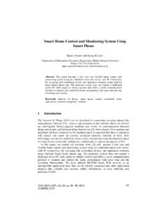
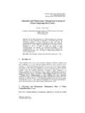
6 With a class -AB bias point (Idq= mA, Vgs= V, and Vgs=28 V) for carrier Amplifier use, it exhibited a Power gain of dB and a high Power -added efficiency (PAE) of % at an output Power of dBm. Ids Vds Time (nsec)Ids (mA)01224364860 Vds (V) Fig. 2. Simulated voltage and current waveforms of the Class-F Power Amplifier . 2024283236404481216202428 Class-F Gain Sim Class-F Gain Exp Class-F PAE Sim Class-F PAE Exp Pout (dBm)Gain (dB)020406080100 PAE (%) Fig. 3. Simulated and measured performances of the Class-F Power Amplifier . 173 Design and implementation of the Doherty Power Amplifier Delay compensation lines Offsetlines Output combinerPinPeaking 90 Input matching50 c 50 p 50 90 50 90 Input matchingHybridcouplerCarrier PAOutput matchingOutput matching Class-F PA * Carrier PA = class -AB biased Class-F PA* Peaking PA = Class-F PA Fig.
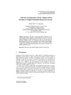
7 4. Schematic of the proposed Doherty Power Amplifier . Fig. 4 is a schematic of the proposed Doherty Power Amplifier that has Class-F load networks for both carrier and peaking amplifiers. The carrier Amplifier is used for 90 input split. The output signals from the carrier and peaking amplifiers are combined through a /4 transmission line which also enables the Amplifier to have a proper load impedance modulation. Fig. 5 shows a photograph of the implemented Doherty Power Amplifier for the 751 MHz LTE band. Overall size of the circuit is 191 120 mm2. While the carrier Amplifier has a class AB bias, the peaking has a class -C bias point (Idq=0 mA, Vgs= V, and Vds=28 V) which allows later turn-on and high peak efficiency. Hybrid coupler3rd harmonic control2nd harmonic controlInput MacthingOutput MacthingOutputoffset lineInputoffset lineInputOutput119 mm120 mm /4 line Fig.
8 5. Simulated and measured performances of the Class-F Power Amplifier . Fig. 6 shows the measured performances for the CW and two-tone excitations. For a 751 MHz CW signal, the Amplifier exhibited a high PAE of % and a gain of 18dB at an output Power of dBm (see Fig. 6(a)). An average output Power of dBm was achieved for a 3rd-order intermodulation distortion (IMD3) of -30 dBc (see Fig. 6(b)). Fig. 7 and 8 show the measured results using an LTE signal Based on 16-qudrature amplitude modulation (16-QAM). A gain of dB and a PAE of % were obtained at an average output Power of dBm which is a dB back-off point (see Fig. 7(a)). At the same back-off point, an adjacent channel leakage Power ratio (ACLR) at 5 MHz offset of dBc and an error vector magnitude (EVM) of % were achieved.
9 Fig. 8 shows the measured Power spectral density (PSD) at an output Power of dBm. 1520253035404591215182124 Class-F Doherty Gain Sim. Class-F Doherty Gain Exp. Class-F Doherty PAE Sim. Class-F Doherty PAE Exp. Pout (dBm)Gain (dB)020406080100 PAE (%) (a) 15202530354045-54-45-36-27-18-9 Class-F Doherty IMD3 Low Sim. Class-F Doherty IMD3 Low Exp. Class-F Doherty IMD3 High Sim. Class-F Doherty IMD3 High Exp. IMD3 (dBc)Pout (dBm) (b) Fig. 6. Simulated and measured performances of the implemented Doherty Power Amplifier : (a) gain and PAE, (b) IMD3. 19152025303540101214161820 Gain PAE Pout (dBm)Gain (dB)020406080100 PAE (%) (a) 152025303540-39-36-33-30-27-24 ACLR EVM Pout (dBm)ACLR (dBc)048121620 EVM (%) (b) Fig. 7. Measured performances using a down-link LTE signal: (a) gain and PAE, (b) ACLR and EVM. dBc735740745750755760765-30-20-100102030 PSD (dBM/Hz)Frequency (MHz)5 MHz offset5 MHz dBc Fig.
10 8. Measured PSD using a down-link LTE signal. 4 Conclusions In this paper, we proposed a Doherty Power Amplifier that has an improved efficiency using the Class-F load networks for the LTE applications at the 751 MHz band. Both carrier and peaking amplifiers have the identical Class-F load network, through they have different bias levels which are class -AB and class -C points for the carrier and peaking amplifiers, respectively. The proposed circuit was implemented and evaluated using CW, two-tone, and down-link LTE modulated signals. It exhibited a very high PAE of with an acceptable ACLR of dBc at an average output Power of dBm which is a dB back-off point. Based on out simulation and experimental results, this method can be used to the Power amplifiers for LTE base transceiver system or RF remote heads.