Transcription of Downflow Conversion Kit - Advanced Distributor Products
1 Downflow Conversion Kit used to Modify Air Handler Units for Downflow Application 0672327-00 February 2015 Installation Instructions 2175 West Park Place Blvd., Stone Mountain, GA 30087 Product improvement is a continuous process at Advanced Distributor Products . Therefore, product specifications are subject to change without notice and without obligation on our part. Please contact your ADP representative or Distributor to verify details. by Advanced Distributor Products . All rights reserved. WARNING Improper installation, adjustment, alteration, service or maintenance can cause personal injury, loss of life, or damage to property. Installation and service must be performed by a licensed professional installer (or equivalent) or a service agency. CAUTION Physical contact with metal edges and corners while applying excessive force or rapid motion can result in personal injury.
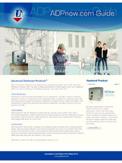
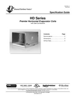
2 Be aware of, and use caution when working near these areas during installation or while servicing this equipment. GENERAL This kit is used to modify air handler units for use in Downflow applications. The procedure requires that the installer remove the evaporator coil and re-install it for Downflow air discharge application. Figure 1 shows the air handler unit as configured at the factory. As shipped, some models are configured for upflow air discharge, and some models are configured for either upflow or horizontal left-hand air discharge. Figure 2 shows the air handler unit after re-configuring for installation in Downflow air discharge applications. NOTE: A Downflow combustible floor base is not required for the applicable air handler. FIGURE 1 As Shipped Configuration Horizontal Drain Connections (both sides; not used) Upflow Drain Pan Horizontal Drain Pan (multi-position models only, to be removed for Downflow application) Upflow Drain Connections FIGURE 2 Insulated Drain Pan Shields Installed Outer Coil Slab Shields Connection Panel Air Handler Access Panel Downflow Configuration Downflow Coil Support Brackets Installed Drain Pan Evaporator Coil in Downflow Configuration Go to your app store and download a free QR Code Reader Scan to see the Downflow Installation Video 2 GENERAL IMPORTANT Increase blower speed on all models for Downflow operation.
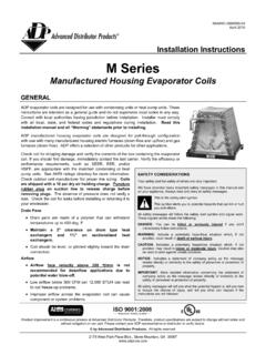
3 See page 8 for details. WARNING The State of California has determined that this product may contain or produce a chemical or chemicals, in very low doses, which may cause serious illness or death. It may also cause cancer, birth defects, or reproductive harm. SHIPPING & PACKING LIST Air Handler Sizes 18 & 24 25, 30, 36 31, 37-60 Figure 3 Parts Part Number 165873190 165873191 165873192 Part Description Quantity Quantity Quantity Insulated drain pan 1 1 1 A Insulated Downflow coil support brackets 2 2 2 B Insulated Inner drain pan drip shields 2 2 2 C Non-insulated outer coil slab shields 2 2 2 D Front and rear insulated air seal plates 2 2 2 E Tapping screws (#8 x 1 AB hex washer HD) for Downflow coil support brackets 6 6 6 F Nylon cable ties (5-1/2 long) for outer coil slab shields 4 4 4 G insulating foam tape for coil suction manifold (16 Long) 1 1 1 H insulating foam tape for blower housing 3 N/A N/A I Wiring diagram 1 N/A N/A J FIGURE 3 Downflow Kit Parts A B C D E F G H I J 3 1.
4 Remove the connection panel, access panel, and the blower panel. Keep all panels and screws; these will be re-used when reassembling. 2. Remove the support bar. Keep the bar and 4 screws for later use. 3. Remove all upflow and horizontal drain pan mounting brackets (Figures 4 and 5). Discard these brackets. 4. Carefully slide the coil and the horizontal drain pan assembly from the air handler cabinet. Discard the horizontal drain pan. 5. Remove the rear coil support bracket (Figure 6); discard. REMOVING COIL FROM HOUSING FIGURE 5 CAUTION Be certain all power has been disconnected from the air handler before beginning work. WARNING Excessive Weight Hazard - Use two or more people when moving and installing the unit. Failure to do so can result in back or other type of injury. FIGURE 4 Remove Upflow Drain Pan Mounting Bracket (18 through 30, and 36) Remove Horizontal and Upflow Drain Pan Mounting Brackets (31, and 37 through 60) Remove Bracket Securing Upflow Drain Pan to Unit Remove Brackets Securing Both Drain Pans to Unit FIGURE 6 Remove Rear Coil Bracket 4 MODIFYING INDOOR COIL 1.
5 Remove 4 screws attaching coil to drain pan (Figure 7). 2. Remove the drain pan from the coil and replace it with the kit-provided insulated drain pan (Part A). Reinstall the 4 screws. 3. Working from the bottom of the coil, install provided insulated drain pan drip shields (Part C, two each) as illustrated in Figure 8. Be sure each is inserted snugly between the drain pan and slab. FIGURE 8 FIGURE 9 Installing Outer Coil Slab Shields 4. Install both outer coil slab shields (Part D, two each) using the provided tie-wraps (Part G, four each) (Figure 9) and secure to return bends on both ends. Ensure the shields are within 1/4 from the drain pan. FIGURE 7 Remove Drain Pan Remove the Four Screws Securing the Coil to the Drain Pan Insulated Drain Pan Drip Shields FRONT BACK 5 MODIFYING INDOOR COIL (CONT.) 5. Wrap the coil suction manifold and TXV bulb with the provided insulating foam tape (Part H) to prevent condensate from dripping or blow off the manifold, as shown in Figure 10.
6 NOTE: Failure to install all shields (steps 3 and 4), or the adhesive back insulating foam (step 5) can result in condensate blow-off and subsequent damage to the building and its contents. A. Insert insulating foam tape behind suction manifold as exampled below. FIGURE 10 insulating Coil Suction Manifold B. Remove backing from insulating foam tape to expose adhesive side as exampled below. C. Fold insulating foam tape over front of the suction manifold as exampled below. 6 MODIFYING AIR HANDLER HOUSING 1. Turn housing upside down. 2. Reinstall the support bar using 4 screws (Figure 11) 3. Sizes 18 & 24 Units Only: Use three strips of the provided insulated tape (Part I) and attach to exposed side of the blower housing (Figure 12). This is required only for these sizes to prevent sweating in Downflow . NOTE: Removing the blower housing to perform this task is optional.
7 NOTE: If the insulated tape covers the wiring diagram, an additional wiring diagram is included in the kit, 4. Using the two insulated coil support brackets (Part B and six #8-18 x 1 screws (Part F) provided in the Downflow kit, install the coil supports brackets to the inner sides of the cabinet (Figures 13 and 14). 5. Position the front and rear insulated air seals (part E) onto the Downflow coil support brackets (Figure 15). Be sure the seals seat against the back and front of the air handler and that the front will seat against the access panel when reinstalled. FIGURE 11 FIGURE 12 Blower Housing Insulated (Sizes 18 & 24) Installing Support Bar 7 MODIFYING AIR HANDLER HOUSING (CONT.) FIGURE 14 Both Coil Support Brackets Installed FIGURE 15 Air Seals Installed 1. Install evaporator coil with insulated drain pan assembly on the Downflow coil support brackets.)
8 2. Re-install the connection panel making sure that the openings are properly aligned with the refrigerant lines. 3. Re-install and fasten the blower panel in the inverted position. 4. Re-install and fasten the access panel. 5. Size 18 & 24 units only: Affix the provided wiring diagram (Part J) to the exterior of the unit access panel. 6. Install converted air handler onto floor opening. Apply sealant as required. 7. Install air filter. FIGURE 16 Installing Coil REINSTALLING IN Downflow CONFIGURATION FIGURE 13 Installing Insulated Coil Support 8 REINSTALLING IN Downflow CONFIGURATION (CONT.) IMPORTANT Increase blower speed on all models for Downflow operation. WARNING Electric shock hazard! - Disconnect all power supplies before servicing. Replace all parts and panels before operating. Failure to do so can result in death or electrical shock.
9 3-Speed PSC Motor 1. For Downflow operation, use the next highest speed setting available. 2. If set to high speed from the factory, use high speed for Downflow . 3. Refer to the air handler installation instructions for details on how to change the blower speed. 5-Speed High Efficiency ECM Motor 1. If factory-set speed tap 3 is desirable for your application, use speed tap 5 for Downflow . 2. If speed tap 2 is desirable for your application, use speed tap 3 in Downflow . 3. Refer to the air handler installation instructions for details on how to change the blower speed. FIGURE 17 Downflow Configuration Access Panel Removed Insulated Downflow Coil Support Insulated Front Air Seal Outer Coil Slab Shields Wrap the Suction Manifold with insulating foam Tape to Prevent Condensation from Forming Factory-Insulated Drain Pan Drip Shields Evaporator Coil in Downflow Configuration Blower Panel Supply (Discharge) Flange Plenum #8-18x1 Screws (3 Each Side) Insulated Downflow Coil Support Insulated Rear Air Seal CHANGE BLOWER SPEED