Transcription of DRAFTING MANUAL
1 Update 69 Gary Whitmire DRAFTING MANUAL Gears (Bevel and Hypoid) DRAFTING Practice section Page 1 August, 2003 Genium Publishing Corporation General This section provides the basis for uniformity in engineering gears drawings and their technical data for gears with intersecting axes (bevel gears), and nonparallel, nonintersecting axes (hypoid gears). It also discusses the method of specifying matched sets on a gear drawing. Purpose It is the purpose of this section to provide formats, nomenclature, and definitions. The minimum data for the various gear types are defined. Where additional data are required, methods for specifying these data are shown. Slight deviations for critical applications are allowed, provided general formats are maintained. Examples - Various types of gears are illustrated by sample drawings. Dimensioning and Notes - Illustrations show only those dimensions which control the gear teeth and their relation to the specified mounting.
2 All other dimensions and specifications shall conform to recommended DRAFTING practice. Dimensional values show the number of decimal places recommended in each instance. Where required to assure calculations, such as for pin measurement or master gears, accurate to the fourth place to the right of the decimal point, it is necessary to specify the base diameter, pitch diameter, helix angle, and non-whole number diametral pitch to eight or seven significant places. Angular Dimensions - All angular dimensions shall be expressed in degrees and decimal portions thereof. (Where desired, the angle may be given in degrees, minutes and seconds.) Applicable Documents The following reference documents contain additional information and should be used when applicable. ASME Abbreviations and Acronyms ASME Decimal Inch. Drawing Sheet Sizes and Format ASME Metric Drawing Sheet Sizes and Format ASME Line Conventions and Lettering ASME Multiview and Sectional View Drawings ASME Dimensioning and Tolerancing ASME Surface Texture Symbols AGMA Gear Nomenclature - Terms, Definitions, Symbols, and Abbreviations Update 69 Gary Whitmire DRAFTING MANUAL Gears (Bevel and Hypoid) DRAFTING Practice section Page 2 August, 2003 Genium Publishing Corporation Gear Drawing Practices Arrangement - The gear drawing shall clearly illustrate the general configuration.
3 The method of manufacture, the quantities involved and the desired inspection method may influence the method of dimensioning. Illustrations of various gear configurations are provided for guidance only and are not mandatory. Gear Data - Gear data shall be grouped as illustrated and shall be presented in the order shown. The location of the gear data on the drawing is optional. Specifying a Diameter For external gears only, the major diameter is specified as the outside diameter and the minor diameter is specified as the root diameter. For internal gears the major diameter is specified as the root diameter and the minor diameter is specified as the inside diameter. This is in keeping with present usage in some segments of the gear industry. Manufacturing Method - The drawing shall clearly depict the product without reference to a manufacturing or inspection method.
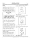
4 This rule may be disregarded only where special situations are involved which do not lend themselves to exact specifications and tool inspection information is necessary for control. Drawing Title - For identification purposes, the title should include the word pinion or gear as applicable. Straight Bevel Gear Teeth Straight bevel gear and pinion teeth are drawn as shown in Figure 1. The mounting distance shown on the drawing is an assembly dimension and is specified as a reference dimension. Update 69 Gary Whitmire DRAFTING MANUAL Gears (Bevel and Hypoid) DRAFTING Practice section Page 3 August, 2003 Genium Publishing Corporation . (.XXX)( )( )Mounting note 1 See note See note 1 See note FACE AAXIS OFMATINGMEMBERNote 1: When face angle distance and back angle distance (See Figure 9) are used for dimensioning the gear blank, the face angle and the back angle should be given as reference dimensions on the drawing without a tolerance.
5 Figure 1. Straight Bevel Gear/Pinion Gear data not included in Figure 1 are tabulated on the drawing as shown in Figure 2. The drawing must also show material and heat treatment specifications. NUMBER OF TEETH XX DIAMETRAL PITCH (See note 1) ( ) PRESSURE ANGLE ( ) PITCH DIAMETER ( ) Update 69 Gary Whitmire DRAFTING MANUAL Gears (Bevel and Hypoid) DRAFTING Practice section Page 4 August, 2003 Genium Publishing Corporation ADDENDUM (.XXX) (See note 2) WORKING DEPTH (.XXX) (See note 2) WHOLE DEPTH . (See note 2) THEORETICAL OUTSIDE DIAMETER ( ) (See note 2) THEORETICAL CROWN TO BACK ( ) (See note 2) PITCH ANGLE ( ) (See note 2) ROOT ANGLE ( ) CIRCULAR THICKNESS (.XXXX) (See note 2) MEAN MEASURING ADDENDUM .XXX (See note 2) MEAN MEASURING THICKNESS . (See note 2) NORMAL BACKLASH WITH MATE . (See note 2) BACKLASH VARIATION TOLERANCE (See note 3).
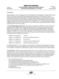
6 XXXX SHAFT ANGLE ( ) FILLET RADIUS . (See note 2) RUNOUT TOLERANCE (See note 3) .XXXX PITCH TOLERANCE (See note 3) .XXXX INDEX TOLERANCE (See note 3) .XXXX TOOTH SURFACE TEXTURE XX AA OR Ra AGMA QUALITY CLASS XX TOOTH FORM CONIFLEX OR REVACYCLE DRIVING MEMBER PINION OR GEAR DIRECTION OF ROTATION CW AND/OR CCW MFG SUMMARY NUMBER XXXXXX PART NUMBER OF MATE XXXXXXXX-X NUMBER OF TEETH IN MATE XX Notes 1. For metric drawings, specify module in place of diametral pitch. 2. For metric drawings, reduce by one the number of decimal places to the right. 3. See , for when to specify these values on the gear drawing. Figure 2. Data Specifications For Straight Bevel Gears Update 69 Gary Whitmire DRAFTING MANUAL Gears (Bevel and Hypoid) DRAFTING Practice section Page 5 August, 2003 Genium Publishing Corporation Spiral Bevel Gear Teeth Spiral bevel gear and pinion teeth are drawn as shown in Figure 3.
7 (.XXX)(.XXX)( )( )Mounting note See note 1 See note FACE OFMATINGMEMBERNote 1: When face angle distance and back angle distance (See Figure 9) are used for dimensioning the gear blank, the face angle and the back angle should be given as reference dimensions on the drawing without a note Figure 3. Spiral Bevel Gear/Pinion Update 69 Gary Whitmire DRAFTING MANUAL Gears (Bevel and Hypoid) DRAFTING Practice section Page 6 August, 2003 Genium Publishing Corporation Gear data not illustrated in Figure 3 are tabulated on the drawing as shown in Figure 4. The drawing must also show material and heat treatment specifications. NUMBER OF TEETH XX DIAMETRAL PITCH (See note 1) ( ) NORMAL PRESSURE ANGLE ( ) MEAN SPIRAL ANGLE ( ) PITCH DIAMETER ( ) ADDENDUM (.XXX) (See note 2) WORKING DEPTH (.XXX) (See note 2) WHOLE DEPTH (.)
8 XXX) (See note 2) THEORETICAL OUTSIDE DIAMETER ( ) (See note 2) THEORETICAL CROWN TO BACK ( ) (See note 2) PITCH ANGLE ( ) ROOT ANGLE ( ) CIRCULAR THICKNESS (.XXXX) (See note 2) MEAN MEASURING ADDENDUM .XXX (See note 2) MEAN MEASURING THICKNESS . (See note 2) MEAN MEASURING DEPTH . (See note 2) NORMAL BACKLASH WITH MATE . (See note 2) BACKLASH VARIATION TOLERANCE (See note 3) .XXXX (See note 2) SHAFT ANGLE ( ) FILLET RADIUS . (See note 2) RUNOUT TOLERANCE (See note 3) .XXXX PITCH TOLERANCE (See note 3) .XXXX INDEX TOLERANCE (See note 3) .XXXX TOOTH SURFACE TEXTURE XX AA OR Ra AGMA QUALITY CLASS XX TOOTH FORM GENERATED OR FORMATE OR HELIXFORM DRIVING MEMBER PINION OR GEAR DIRECTION OF ROTATION CW AND/OR CCW MFG SUMMARY NUMBER XXXXXX Update 69 Gary Whitmire DRAFTING MANUAL Gears (Bevel and Hypoid) DRAFTING Practice section Page 7 August, 2003 Genium Publishing Corporation PART NUMBER OF MATE XXXXXXXX-X NUMBER OF TEETH IN MATE XX V AND H CHECK IN THOUSANDTHS OF AN INCH (OR HUNDREDTHS OF A MILLIMETER) FOR FINISHED GEARS (See note 4).
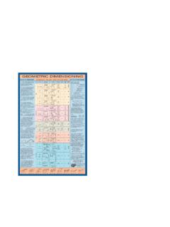
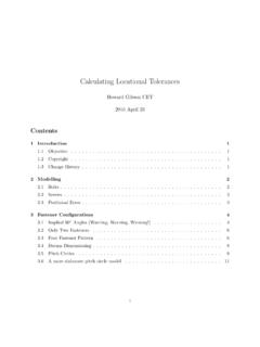
9 Gear Convex Toe Heel Total V XX XX XX H XX XX XX Gear Concave Toe Heel Total V XX XX XX H XX XX XX Notes 1. For metric drawings, specify module in place of diametral pitch. 2. For metric drawings, reduce by one the number of decimal places to the right. 3. See , when to specify these values on the gear drawing. 4. May be specify on matched set drawing. (See Figure 8) Figure 4. Data Specifications For Straight Bevel Gears Update 69 Gary Whitmire DRAFTING MANUAL Gears (Bevel and Hypoid) DRAFTING Practice section Page 8 August, 2003 Genium Publishing Corporation Hypoid Gear Teeth Hypoid pinion and gear teeth are drawn as shown in Figures 5 and 6, respectively.. (.)
10 XXX)( )Mounting note 1 See note 1 See note FACE APEXROOT APEXCROSSING POINTAXIS OFMATINGMEMBERNote 1: When face angle distance and back angle distance (See Figure 9) are used for dimensioning the gear blank, the face angle and the back angle should be given as reference dimensions on the drawing without a note (.XXX).XXX A - B Figure 5. Hypoid Pinion Update 69 Gary Whitmire DRAFTING MANUAL Gears (Bevel and Hypoid) DRAFTING Practice section Page 9 August, 2003 Genium Publishing Corporation (.XXX)(.XXX)( )Mounting note 1 See note See note FACE APEXROOT APEXCROSSING POINTPITCH OFMATINGMEMBERNote 1: When face angle distance and back angle distance (See Figure 9) are used for dimensioning the gear blank, the face angle and the back angle should be given as reference dimensions on the drawing without a See note 1 Figure 6.