Transcription of Drainage Below Ground Stormwater Sizing Drains and …
1 Technical Solution Sheet 4: Drainage ( Below Ground Stormwater ). Duplicate solution of Roof Plumbing (Roof and Stormwater ). Roof and Stormwater AIM SURFACE Drainage SYSTEMS DESIGN. The aim of this technical solution is to clarify the AS/NZS requirements for Sizing Stormwater Drains and Summary of methods to design surface eaves gutters. Drainage systems PLUMBING REGULATIONS 2008 Two methods of design are used depending on The Plumbing Code of Australia (PCA) is adopted the area of the proposed allotment: by and forms part of the Plumbing Regulations 2008. Part D1 of the PCA specifies the objectives 1. Nominal method for single dwellings (rural).
2 And performance requirements related to the and single dwellings (urban) where the installation of roof Drainage systems. AS/NZS allotment size is less than 1000m . This method Plumbing and Drainage - Part 3: does not involve any calculations and some Stormwater Drainage & Section 2 of AS/NZS rules are provided regarding diameter of pipes, Plumbing and Drainage - Part 5: depth of cover, gradient and layout. Housing installations are Deemed to Satisfy . documents listed in Part B3 of the PCA and both 2. General method for all buildings. This method contain sections on Surface and Roof Drainage involves hydraulic design calculations to Systems - design.
3 Determine design flows, and procedures to determine the design of channels and Drains . The Plumbing Regulations 2008 also specify that roofing ( Stormwater ) work must comply with Nominal method - Minimum diameter of pipe SAA/SNZ HB114 Guidelines for the design of 1. For single dwellings in rural areas, and single eaves and box gutters. dwellings on urban allotments with areas less than 1000m , the minimum diameter of pipe Part D2 of the PCA specifies the objectives and shall be DN90; and performance requirements related to the installation of surface and subsurface Drainage 2. For other properties, downstream of a systems. Stormwater or inlet pit, shall be the greater of- the diameter of the largest pipe entering the pit, AS/NZS is a deemed to satisfy or - DN150.
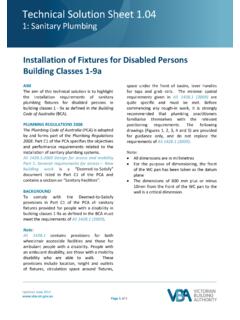
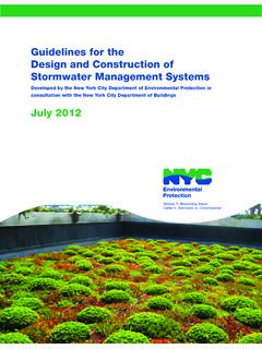
4 Document listed in Part D2 of the PCA and contains sections on Roof Drainage systems Note: Surface Drainage systems - design , Roof An exception to this is at footpath crossings Drainage systems installation , Surface Drainage where multiple pipes of DN100 or less may be systems design and Surface and subsoil used. Drainage systems - installation . Updated December 2015. Page 1 of 6. Technical Solution Sheet External connections Solution The external connection can be to the street 1. The layout should comply with AS/NZS. gutter, a street Drainage pipe or inter-allotment so that the overland flow path is drain (see Figure 1). directed away from the building.
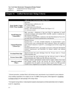
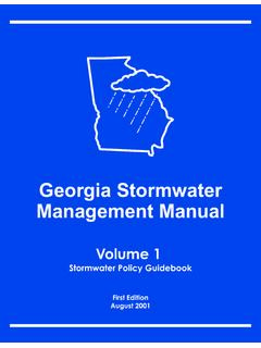
5 Layout of systems 2. The Stormwater Drains are sized in AS/NZS lists a range of requirements for accordance with AS/NZS as follows: the layout of Stormwater Drains . It is important between a downpipe outlet and a to consider: Stormwater or inlet pit, DN90. between the Stormwater pits A & B, DN150;. 1. The allowance for possible Stormwater and discharges from adjacent properties, between pit B and the street kerb, two Drains of DN100 or less 2. Protection of buildings, and 3 Minimum cover for PVC-U from 3. The location of Stormwater Drains in AS/NZS relation to the sanitary Drainage system. under the paved driveway within the property, 75mm Below the underside of Example of layout and Sizing brick or unreinforced concrete for light Figure 2 is from Appendix K of AS/NZS vehicle loadings.
6 Elsewhere for single which details a solution to Stormwater Drainage dwelling properties 100mm. on an urban allotment not exceeding 1000m . under the paved footpath outside the The Drainage system is constructed of approved property, 75mm Below the underside of the non-metal materials. paving. FIGURE 1 TYPICAL ARRANGEMENT OF INLET PIT AND FOOTPATH CROSSING. Updated December 2015. Page 2 of 6. Technical Solution Sheet 4. The minimum gradient for Stormwater Drains (from AS/NZS ) for DN90, DN100 and FIGURE 2 SOLUTION TO. DN150 is 1:100. Stormwater DRANAGE ON URBAN. ALLOTMENT. 5. Stormwater pits, A & B are sized based on AS/NZS Each pit would be 450mm x 450mm with a minimum fall of 20mm between the invert of the inlet and outlet.
7 ROOF Drainage SYSTEMS DESIGN. AS/NZS & SAA/SNZ HB114. Elements of Roof Drainage Design 1. Catchment areas Vertical walls abutting a roof must be included in the catchment area. For hipped roofs with eaves gutters a simplified formula can be used to calculate catchment area, but the slope of the roof must be known. Refer to AS/NZS and SAA/SNZ HB114. which simplify the roof catchment calculations. (see Appendix A) SAA/SNZ. HB114 for example calculations for typical roof styles. (see page 14 step 2) for the method using the slope factor for a pitched roof to an eaves gutter (hip & valley with no abutting vertical walls or flat roofs). The catchment area of a roof and any vertical walls is greatly influenced by the direction of wind driven rain, therefore the combined catchment area must be used for Sizing purposes.
8 2. Rainfall intensity Rainfall intensities are given in Appendix E. AS/NZS The appendix gives five minute duration rainfall intensities. There is also reference to an Average Recurrence Interval (ARI) of 20 and 100 years. For example: external gutters eaves gutters 20 years ARI. The ARI is used in accordance with Table Internal gutters, box gutters 100 years ARI. AS/NZS where the risk of property damage, inconvenience or injury to Note: people is taken into account For a 500 year ARI, multiply 100 year ARI x Table E1 lists latitude and longitude of selected places, some of which are marked on the maps. If there is any doubt regarding Updated December 2015.
9 Page 3 of 6. Technical Solution Sheet the rainfall intensity for a particular area, Step 3: Determine downpipe size refer to the relevant council / shire for From Table in AS/NZS , or Table accurate rainfall intensity figures. in SAA/SNZ HB114, the minimum size downpipes compatible with spouting of 3. Overflow measures for eaves gutters 6125mm cross sectional area (installed at a Always consider what will happen if the 1:500 gradient) are 90mm diameter round or gutter overflows. If water cannot flow back 100mm x 50mm rectangular. into the building, gutter fixed to rafters without eaves linings, no overflow measures Note: are required. If water can flow back into the A minimum gradient of 1:500 is preferred.
10 Building; through eaves linings, then overflow methods must be provided. Step 4: Select 100 x 50 rectangular downpipe. Blockages can occur in eaves gutters From Figure (B) in AS/NZS or Figure anywhere along the gutter; therefore an 4 in SAA/SNZ HB114 the maximum catchment overflow device at the outlet may not per downpipe is 47m . prevent such overflows. Examples of acceptable overflow measures Step 5: Determine minimum number for eaves gutters can be found in Appendix of downpipes G of AS/NZS To calculate the minimum number of Simplified ways of providing for overflow of downpipes, divide the roof catchment external eaves gutters can also be found in area by the allowable maximum SAA/SNZ HB114.