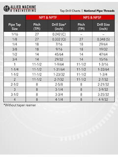
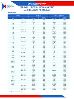
Transcription of Drill string and components Table DS-1
1 Drill STRINGDS 1 Copyright 2015 IADC Drilling ManualDrill string and componentsThis chapter of the IADC Drilling Manual is concerned with the specifications, operating data, and the care and handling of Drill string . It will also discuss troubleshooting of the prob-lems that may IADC definition of a Drill string is drillpipe with tool joints attached. Drill stem is all those members between the swivel and the bit, and it includes Drill string , kelly or top drive, subs, Drill collars, heavy weight drillpipe, stabilizers, shock absorbers, reamers and any other in-hole equipment used generally or part-time during drilling operations. API/ISO specificationsIn the worldwide oil industry today, an overwhelming major-ity of all tubular goods are manufactured to specifications developed and approved by the American Petroleum Insti-tute.
2 These specifications cover the mechanical properties of the steel, the details of manufacture and physical dimen-sions of the pipe . The latter include internal and external diameters, wall thickness, and upset dimensions for each nominal size, weight and grade, as well as tool joint type, OD and ID, and length. API Specification 5DP covers Drill - pipe . Bulletins 5A2, 5C2, and 5C3 cover aspects of the use of and care of drillpipe wall thickness or that joints would mate with similar products manufactured by different mitigate the resulting confusion and loss of time, the API was induced to undertake a program of standardization and mark-ing. This program is a continuing one which enables changes to occur based upon improved technology and the needs of users and manufacturers to be disseminated to the industry in a minimum amount of time and with a high degree of accuracy.
3 API Specifications and Recommended Practices cover a wide range of oilfield equipment in addition to tubular goods. These publications are revised as necessary and constitute one of the best sources of information on the design, manufacture, care, and use of drilling and production section of the Drilling Manual relates not only to the API 5DP specifications, but also to Recommended Practice RP7G and RP7A1. These publications relate to the connec-tions for the Drill string and also to the design and operating limits of the Drill section of the Drilling Manual discusses Drill string care and use and gives examples of the types of problems usually encountered when the Drill string is improperly used or used beyond its physical capabilities. This section also recom-mends practices which will overcome or eliminate the prob-lems often encountered when using the Drill the oil industry today, most drillpipe is manufactured to specifications developed and approved by API/ISO.
4 This includes mechanical properties of the steel and physical di-mensions of the tubes and their tolerance on yield strength of drillpipe tubes is plus 30,000 psi. All grades above E-75 are referred to as high strength. Grades marked with an asterisk have been used ,but not been formally production of high-strength Drill - pipe tube began in the 1950s. When high strength tubes were accepted by API some 10 years later, tool joint dimensions (ODs and IDs) were those commonly used on E75 tubes. A committee was appointed, and tool-joint dimensions recommended, with the result that the torsional yield of the tool-joint pin was at least 80% as strong as the tube to which it was to be attached. Good practice is for the tool-joint box to be stronger than the pin initially, because wear will ultimately make the box the weaker attaching of tool joints to upset drillpipe tubes by flash welding was replaced in the 1970s by inertia and friction welding.
5 API/ISO specifications require the weld to be stronger than the tube body, have good ductility, and not be harder than 37 Rockwell sizes of Drill - pipe tubes come in light weight, standard weight, and one or more heavier than standard weights. Both the grade code and the weight code should be sten-ciled on the pin base for finished Drill string assemblies. It is recommended that these two codes (grade and weight) also be stenciled on a milled flat on the pin tong surface for quick identification. The numeric code is 1 for a light-weight tube and 2 for a standard weight tube. Heavier-than-standard tubes receive a 3, 4, or 5. Most of the tubes today are stan-dard weight, and these receive the 2 designation. A complete Table DS-1: Drill pipe GradesGrade CodeMinimum Yield (psi)E-75E75,000X-95X95,000G-105G105,000 S-135S135,000Z-140*Z140,000V-150*V150,00 0U-165*U165,000 Drill pipe tubes are furnished in the following API length ranges: Range 1: 18-22 ft; Range 2: 27-30 ft; Range 3: 38-45 2 Drill STRINGC opyright 2015 IADC Drilling Manuallist of these may be found in API 5DP in Table C-12.
6 Drill string nomenclature and abbreviations are detailed in Table description and basic theoryGeneral informationThe Drill string is required to serve three basic functions: Transmit and support axial loads; Transmit and support torsional loads; Transmit design parameters and a step-by-step procedure of designing a string are given in API RP 7G, 16th ed, Section 7. Another recommended source document is G. K. McK-own, Drill string Optimization for High-Angle Wells, 1989 SPE/IADC Drilling Conference, SPE/IADC drillpipe is offered in the grades listed below under Mechanical Properties API Steel Drill pipe . The Drill string is used to transmit power by rotary motion from surface to a Drill bit at the bottom of the hole, to convey flushing media to the cutting face of the tool, and to carry cuttings out of the hole. Thus, it plays a vital part in the successful drilling of oil and gas are commonly used abbreviations for Drill - pipe upsets: IU: Internal upset; EU: External upset; IEU: Internal-external the exception of specialty tools, probably no other part of the Drill stem is subjected to the complex stresses which Drill string must withstand.
7 For this reason, the combined skills of steel-industry engineers, with full cooperation from oil companies and drilling contractors and in conjunction with API and IADC, have been used in the development of this vi-tal tool. The same skill was utilized in formulating suggested practices in the care and handling of pipe on the surface, while making trips in and out of the hole and while drilling. With this information, contractors and operators can extend Drill - string life and realize inprove project string is an important and expensive part of the rig, but suffers from a relatively short life. The cost of the Drill string places it in the category of a capital investment. It is not strictly expendable. A recommended practice, followed by many contractors, is to identify each joint upon purchase with an alpha-numeric serial. This serial number, along with the length of the joint, should be recorded when it is placed Table DS-2: Tool joint codeDescriptionIFInternal FlushEH or XHExtra HoleSHSlim HoleOHOpen HoleSL - H-90 Slim Line-Hughes-90 FHFull HoleH-90 Hughes-90 WOWide OpenNCNumbered ConnectionFigure DS-1: Weld-on tool joint.
8 The flash-welded tool joint, introduced in 1938, was the industry s first weld-on tool. Inertia welding was introduced in 1974 and continuous-drive friction welding in DS-3: Interchangeability chart for tool flush2 3/82 7/83 1/244 1/2 Full hole4 Extra hole3 1/24 1/25 Wide open3 1/245 Slim hole2 7/844 1/2 Table DS-4: Mechanical properties of API steel Drill Strength (minimum psi)75,00095,000105,000135,000 Yield Strength (maximum psi)105,000125,000135,000165,000 Tensile Strength (minimum psi)100,000105,000115,000145,000 Drill STRINGDS 3 Copyright 2015 IADC Drilling Manualin the string . This practice, along with field support and of-fice accounting, will facilitate: Determining the useful life of the joint; Recording types of service and stresses the joint might be exposed to; Switching within the string to optimize use; Determining causes of failures more accurately; Preventing or minimizing downhole and lengths of steel drillpipeAs discussed in API/ISO Specifications above, drillpipe tubes are furnished in the following API length ranges: Range 1: 18-22 ft; Range 2: 27-30 ft; Range 3: 38-45 identification is marked at the base of the pin by the tool joint manufacturer after the pin is affixed.
9 The marking will be in accordance with Figure DS-2. It is further recom-mended that drillpipe other than standard weight Grade E-75, be marked according to Figures DS-3 through DS-5. This is to give the crew rapid identification of high strength drillpipe on the racks and on the floor during trips when it is in a combination string with Grade E-75. With little trouble, if necessary cleaning out the milled slot, the specific grade and weight can be determined from the stenciled figures. joint OD surfaces should be performed, with an emphasis on detection of longitudinal cracks. In highly stressed drilling environments or if evidence of fatigue damage is noted, magnetic particle inspection should be made of the entire box threaded area, especially the last engaged thread area, to determine if transverse cracks are present. The wet fluorescent magnetic particle method is tool joint description/basic theoryThe flash welded tool joint was the first weld-on type tool joint introduced to the industry in 1938.
10 Inertia welding was offered in 1974 and continuous-drive friction welding in 1978. Figure DS-1 illustrates weld-on tool inertia and continuous-drive friction welders use fric-tional heat for achieving welding temperatures. However, the inertia welder uses a flywheel and momentum principle, whereas the continuous drive-friction welder maintains a constant rpm motor and brake selectionFor many years tool joints have had a minimum yield strength of 120,000 psi. The old IF, XH, FH, etc., have been replaced with Numbered Connection series - NC plus a number in-Figure DS-2: Tool joint markings for component identification. Note: Pin base marks should be clear and legible and not struck over with manufacturing 6 07 YY E 1 NC50 Markings at base of pin: ZZ 6 07 YY E 1 NC50 Tool joint mfctr: ZZ (ZZ Co.)Month welded: 6 (June)Year welded: 07 (2007) pipe upsetter/processor YYPipe grade: EPipe weight code 1 Tool-joint type: NC50 Drill pipe grades Grade SymbolE-75 EX-95 XG-105 GS-135 SV-150 VFigure DS-3: Identification of standard weight high strength Drill pipe .