Transcription of Dry System Technical Manual for Operation, Maintenance …
1 Dry System Technical Manual for Operation, Maintenance and troubleshooting February, 2010 Form No. F_010608. Page II February 12, 2010. DRY pipe sprinkler Technical DATA. System The Viking Corporation, 210 N Industrial Park Drive, Hastings MI 49058. Telephone: 269-945-9501 Technical Services: 877-384-5464 Fax: 269-818-1680 Email: Table of Contents Page I. System Description 5. A. Model F-1 and F-2 Dry Valves 7. B. Model G-2000, G-3000, and G-4000 Dry Valves 7. II. System components & requirements 8. A. Model F-1 and F-2 Dry Valves 9. B. Model G-2000, G-3000, and G-4000 Dry Valves 11. C. Water Supply 13. D. Size of Systems 13. E. Dry System Water Delivery 14. F. Auxiliary Drains 15. G. Location and Protection of Dry Pipe Valves 15. H. Quick-Opening Devices - Accelerators, Antiflood Devices 16. I. Air Pressure and Supply 18. 1. Description 18. 2. Air Supply 19. 3. Maintenance of Air Pressure 19.
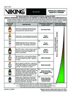
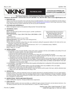
2 4. Air Supply Connections 20. 5. Design Considerations 21. V. System Operation 25. A. Dry Valve Operation 26. B. Accelerator and Antiflood Device Operation 29. VI. Placing the System in service 31. VII. normal conditions 35. VIII. abnormal conditions 35. Ix. inspections, tests, and Maintenance 40. A. Dry Valve Maintenance 40. B. Accelerator Maintenance 47. C. Model B-1 Antiflood Device Maintenance 55. appendix a: Rules of thumb-dry System design and water delivery 60. appendix b: sizing air compressors 65. February 12, 2010 Page . DRY pipe sprinkler Technical DATA. System The Viking Corporation, 210 N Industrial Park Drive, Hastings MI 49058. Telephone: 269-945-9501 Technical Services: 877-384-5464 Fax: 269-818-1680 Email: Figure 1a: Dry System with a Model F-1 or F-2 Dry Valve and Trim Page February 12, 2010. DRY pipe sprinkler Technical DATA. System The Viking Corporation, 210 N Industrial Park Drive, Hastings MI 49058.
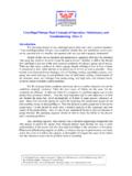
3 Telephone: 269-945-9501 Technical Services: 877-384-5464 Fax: 269-818-1680 Email: Figure 1b: Dry System with a Model G Series Dry Valve and Trim (Model G-4000 shown). February 12, 2010 Page . DRY pipe sprinkler Technical DATA. System The Viking Corporation, 210 N Industrial Park Drive, Hastings MI 49058. Telephone: 269-945-9501 Technical Services: 877-384-5464 Fax: 269-818-1680 Email: NOTE: Sprinkler systems are engineered to meet the standards of NFPA 13, FM Global, Loss Prevention Council (FOC), Assemblee Pleniere, Verband der Sachversicher- er (VdS) or other similar organizations, and will also need to comply with the provisions of governmental codes, ordinances, and standards where applicable. The System must be designed by qualified design professionals in conjunction with insuring bodies. The user is responsible for the design and configuration of the System , its appropriateness for the use intended and its compliance with all standards, codes and ordinances.
4 Viking Corporation does not design systems for specific installations and makes no representation or warranty concerning whether any specific System installation will be sufficient for the intended use or will comply with any standard, code, or ordinance. Any System depicted in this Manual is shown for illustrative purposes only. I. System Description The Dry Pipe Sprinkler System is a fire-protection System that utilizes water as an extinguishing agent, while the System piping from the Dry Pipe Valve to the automatic fusible sprinklers is filled with pressurized air or nitrogen. Dry pipe systems should be installed only where heat is not adequate to prevent freezing of water in all parts of, or in sections of, the System . Air pressure must be lost from the System to trip the valve. Then water must travel through the piping network to the sprinklers (refer to Figures 1a and 1b). Dry pipe systems require frequent inspections, testing, and Maintenance in accordance with NFPA 25.
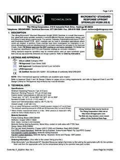
5 The following must be considered: System air pressure Low point drainage Dry pipe valve operation Accelerator operation Valve room temperature Figure 2. Page February 12, 2010. DRY pipe sprinkler Technical DATA. System The Viking Corporation, 210 N Industrial Park Drive, Hastings MI 49058. Telephone: 269-945-9501 Technical Services: 877-384-5464 Fax: 269-818-1680 Email: Although NFPA 13 doesn't require a build- ing or portions of a building to be heated to accommodate the dry pipe sprinkler System , NFPA 13 does require that the valve rooms for dry pipe systems be heated. Minimized use of dry pipe systems is preferred where speed of operation is important. This Technical Manual will cover the Viking dry pipe valve, its trim parts, and their func- tions as well as describe the operation, main- tenance, and repair of valves and System devices. Viking dry pipe valves are available in three configurations; the Model F-1, F-2, or Model G Series Dry Pipe Valves (Figure 2).
6 The dry pipe System uses a moderate supply of air or nitrogen pressure in the sprinkler pip- ing to control a higher water supply pressure and keep the dry valve in a set condition. Figure 3a Figure 3b Figure 3c February 12, 2010 Page . DRY pipe sprinkler Technical DATA. System The Viking Corporation, 210 N Industrial Park Drive, Hastings MI 49058. Telephone: 269-945-9501 Technical Services: 877-384-5464 Fax: 269-818-1680 Email: A. Model F-1 and F-2 Dry Valves Rated to 175 PSI ( Bar) Water Working Pressure A lower air pressure is able to keep the valve closed against the higher water pressure due to a dif- ference in the surface area of the clapper, on which the respective pressures are applied (Figure 3a). The differential is created through the clapper assembly of the dry valve itself. The clapper is latched, creating a positive mechanical seal. The area exposed to pressure above the clapper is considerably larger than the area exposed to pressure below the clapper when the clapper is in the set position (Figure 3b).
7 The area in between, the intermediate chamber (see Figure 3c), is vented to atmosphere. It's important that air is constantly vented to the atmosphere because any pressure buildup in the intermediate chamber will act to over- come the differential (Figure 3c). CAUTION: Do not perform hydrostatic test with the dry valve closed! B. Model G-2000 - G-4000 Dry Valves Rated to 250 PSI ( Bar) Water Working Pressure The pilot operated Model G-2000, G-3000, and G-4000 Dry Valves (Figure 4a) com- bine an internal diaphragm assembly that is pressurized closed with priming water, an internal check valve to isolate the sprinkler System piping (Figure 4b) and a differential valve located on the valve trim that allows the valve to operate upon loss of air pressure (Figure 4c). When the air pressure in the dry pipe System is reduced sufficiently upon the differential valve due to a sprinkler head operation to destroy the pressure differential, the differential valve will open and relieve the priming pressure from the internal diaphragm as- sembly.
8 The internal diaphragm assembly will compress, which will allow water to pass through the body of the valve and center of the internal check valve, entering the sprinkler System piping. Figure 4a Page February 12, 2010. DRY pipe sprinkler Technical DATA. System The Viking Corporation, 210 N Industrial Park Drive, Hastings MI 49058. Telephone: 269-945-9501 Technical Services: 877-384-5464 Fax: 269-818-1680 Email: Figure 4b Figure 4c II. System components & requirements Viking Dry Pipe Valves must be installed in the vertical position only. Connections are provided on the System side of the valve for the air supply (Figure 5) and for a valve room sprinkler (Figure 6). Figure 5 Figure 6. February 12, 2010 Page . DRY pipe sprinkler Technical DATA. System The Viking Corporation, 210 N Industrial Park Drive, Hastings MI 49058. Telephone: 269-945-9501 Technical Services: 877-384-5464 Fax: 269-818-1680 Email: A.
9 Model F-1 and F-2 Dry Valves A connection is also provided for a draw valve (Figure 7) to remove excess prime water. NOTE: Viking's dry valves may be primed with water, except where hard water causes corrosion problems. For Model F-1 and F-2 Dry Valves, if priming water is used, fill the valve with water to the bottom of the face plate. Inspect the drip check valve to be sure priming water isn't leaking through to the inter- mediate chamber (Figure 8). Figure 7 Figure 8. Connections for the optional accelerator (Figure 9) and antiflood device assemblies are provided on the air supply trim (Figure 10). Notice that the intermediate chamber has a connection with the alarm line and facilities for an automatic drip check (Figure 11). Figure 9. Page 10 February 12, 2010. DRY pipe sprinkler Technical DATA. System The Viking Corporation, 210 N Industrial Park Drive, Hastings MI 49058. Telephone: 269-945-9501 Technical Services: 877-384-5464 Fax: 269-818-1680 Email: Figure 10.
10 Figure 11. February 12, 2010 Page 11. DRY pipe sprinkler Technical DATA. System The Viking Corporation, 210 N Industrial Park Drive, Hastings MI 49058. Telephone: 269-945-9501 Technical Services: 877-384-5464 Fax: 269-818-1680 Email: The automatic drip feature plays an important role by allowing small amounts of water or air to escape past the clapper and to remove it from the valve without developing pressure in the intermediate chamber by depressing the plunger. Such pressure would disrupt the valve differential ratio, which might cause the valve to trip. There is also a connection between the intermediate chamber and the optional accelerator and the antiflood device. The supply side of the valve has connections for an alarm test line and a flow test valve (Figure 12). B. Model G-2000, G-3000, and G-4000. Dry Valves For proper operation and approval, the valve must installed as trimmed from the factory.