Transcription of ds farm - High Efficiency Power Solutions
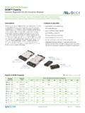
1 Filter/Autoranging Rectifier Module Up to 1000 WattsFARM Rev 1 of 11 06/2017 800 SNRTLCUSCUS Actual x x in57,9 x 55,9 x 12,7 mmFeatures & Benefits RoHS compliant (with F or G pin style) EMI filtering Choice of 500W or 750W modules 96% Efficiency Autoranging 115/230 VAC input Microprocessor controlled Inrush current limiting Mini sized package Power fail signal Module enableProduct HighlightsThe farm (Filter/Autoranging Rectifier Module) is an AC front-end module which provides EMI filtering, autoranging line rectification and inrush current limiting.
2 The farm is available in either 500/750W or 750/1000W models in a mini sized package measuring only x x .The farm interfaces directly with worldwide AC mains and may be used with Vicor 300V input DC-DC converters to realize an autoranging, high density, low profile switching Power supply. The farm includes a microcontroller that continuously monitors the AC line to control bridge / doubler operation. The user need only provide external capacitance to satisfy system hold-up 2nd Generation packaging technology offers flexible mounting options for various manufacturing processes.
3 The farm may be installed as a conventional leaded device for onboard applications, inboard for low profile, height restricted applications, socketed or surface mounted with optional ModuMate interconnect Rating Unit NotesL to N voltage 264 VAC Continuous 280 VAC 100ms+OUT to OUT voltage 400 VDC B OK to OUT voltage 16 VDC EN to OUT voltage 16 VDC Mounting torque 4 6 ( ) in-lbs (N-m) 6 each, 4-40 screwOperating temperature 40 to 100 C H-GradeStorage temperature 55 to 125 C H-GradePin soldering temperature 500 (260) F ( C) <5sec; wave solder 750 (390) F ( C) <7sec.
4 Hand solderOutput current ABaseplate temperature 100 CAbsolute Maximum RatingThermal Resistance and CapacityParameter Min Typ Max UnitBaseplate to sink flat, greased surface C/Watt with thermal pad (P/N 20264) C/WattBaseplate to ambient Free convection C/Watt 1000 LFM C/Watt farm 1 C 1 1 ProductType 1 = 500/750W 2 = 750/1000 WBaseplate 1 = Slotted 2 = Threaded 3 = Thru holePin Style 1 = Short Pin 2 = Long Pin S = Short ModuMate [1] N = Long ModuMate [1] F = Short RoHS [1] G = Long RoHS [1] K = Extra Long RoHS [2]Product Grade Temperatures ( C)
5 Grade Operating Storage E = 10 to +100 20 to +125 C = 20 to +100 40 to +125 T = 40 to +100 40 to +125 H = 40 to +100 55 to +125 Part Numbering[1] Pin styles S, N, F & G are compatible with the ModuMate interconnect system for socketing and surface mounting[2] Not intended for socket or Surfmate mountingFARM Rev 2 of 11 06/2017 800 FARM1xxx FARM2xxxParameter Min Typ Max Min Typ Max Unit NotesOutput Power 0 500 0 750 Watts 90 132 VAC 0 750 0 1000 Watts 180 264 VACE fficiency 94 96 94 96 % 120/240 VAC Output voltage 250 370 250 370 VDC 90 264 VACE xternal hold-up capacitance
6 1,750 F 2 3,300 F in series; HUB3300-S 1,100 F 2 2,200 F in series; HUB2200-SOUTPUT SPECIFICATIONSP arameter Min Typ Max Unit NotesOperating input voltage low range 90 132 VAC Autoranging (doubler mode) high range 180 264 VAC Autoranging (bridge mode)Input undervoltage 90 VAC No damageAC line frequency 47 63 Hz C-Grade 47 880 Hz T-Grade, H-GradePower factor Dependent on line source impedance, hold up capacitance and current 30 Amps 264 VAC peak lineINPUT SPECIFICATIONS (FARM1xxx, FARM2xxx)
7 Electrical CharacteristicsElectrical characteristics apply over the full operating range of input voltage, output Power and baseplate temperature, unless otherwise specified. All temperatures refer to the operating temperature at the center of the baseplate. Specifications apply for AC mains having up to 5% total harmonic PIN SPECIFICATIONSP arameter Min Typ Max Unit NotesAC Bus OK (B OK) Low state resistance 15 To negative output Bus normal Low state voltage VDC Bus normal 50mA max.
8 high state voltage VDC Bus abnormal, 27k internal pull up to 15 VDC (see Figure11) B OK true threshold 235 240 245 VDC Output Bus voltage (see Figure 8) B OK false threshold 200 205 210 VDC Output Bus voltageModule Enable (EN) Low state resistance 15 To negative output Converters disabled Low state voltage VDC 50mA max. high state voltage 12 14 16 VDC 150k internal pull up to 15 VDC (see Figure 10) Enable threshold 235 240 245 VDC Output bus voltage (see Figure 8)
9 Disable threshold 185 190 195 VDC Output bus voltageAC Bus OK - Module Enable, 12 14 16 VDC AC Bus OK and Module Enable thresholds trackdifferential error** Tracking error between BUS OK and Enable thresholdsFARM Rev 3 of 11 06/2017 800 Characteristics (Cont.)GENERAL SPECIFICATIONSP arameter Min Typ Max Unit NotesMTBF >1,000,000 Hours 25 C, Ground Benign, MIL-HDBK-217 FBaseplate material AluminumCover Ends: Zenite 6130 Center section.
10 Kapton insulated aluminumPin Material Style 1 & 2 Copper, Tin / Lead plated Styles S & N (ModuMate compatible) Copper, Nickel / Gold plated Styles F & G (RoHS compliant) Copper, Nickel / Gold platedWeight Ounces (88) (grams)Size x x Inches (57,9 x 55,9 x 12,7) (mm)SAFETY SPECIFICATIONS (FARM1xxx, FARM2xxx)Parameter Min Typ Max Unit NotesIsolation voltage (IN to OUT) None Isolation provided by DC-DC converter(s)Dielectric withstand 2,121 VDC Baseplate earthed(I/O to baseplate)