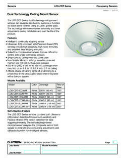
Transcription of Dual Technology Ceiling Mounted Line Model # …
1 Installation InstructionsModel # OAC-DT-2000-MVModel # OAC-DT-2000-DMVDual Technology Ceiling Mounted LineVoltage Occupancy Sensor Read all instructions on both sides of this sheet first Install in accordance with ALL local codes For indoor use onlyPower Requirements:120 to 347 VAC, 50/60 Hz - Neutral Required 120 VAC: Incandescent/Tungsten - 0 to 800W, 50/60 Hz Fluorescent/Ballast - 0 to 1200W, 50/60 HzMotor Load: HP @ 125 VAC230 VAC: Fluorescent/Ballast - 0 to 1200W, 50/60 Hz277 VAC: Fluorescent/Ballast - 0 to 2700W, 50/60 Hz347 VAC: Fluorescent/Ballast - 0 to 1500W, 50/60 HzOperating Environment: Temperature: 32 F 104 F (0 C 40 C) Relative Humidity: up to 90% non-condensingUltrasonicActivated The OAC-DT Ceiling Mount line Voltage Occupancy Sensor is a Passive Infrared (PIR) and Ultrasonic (US) motion sensing lighting control, used for energy savings and convenience.
2 PIR is used to turn the lights ON and then either Technology is used to keep the lights ON. The sensor includes self-adaptive Technology that continually adjusts to conditions by adjusting sensitivity and time delay in real-time. The maximum coverage area may vary somewhat according to room shape and the presence of obstacles. Decrease total coverage area by 15% for soft rooms (for example, heavy draperies or heavy carpeting). The sensor must have a clear view of the area to be controlled. The sensor will not see through glass. Mounting height should not exceed 12 feet.
3 Optimum mounting height is 8 to 10 feet. Mount the sensor so the grills face the open portion of the room and are not facing a nearby wall, door, window, or other obstructing object. Avoid pointing into hallways. Mounting at fixture height is most effective. *To prevent false activation, the sensor should be Mounted away from the air supply duct a minimum of 4 to 6 feet. The OAC-DT sensor can be Mounted to a standard deep x 4 octagon or deep x 4 foursquare electrical boxes (foursquare box requires a two-gang mud ring).CAUTION: Before installing or performing any service on a Greengate system, the power MUST be turned OFF at the branch circuit breaker.
4 According to NEC 240-83(d), if the branch circuit breaker is used as the main switch for a fluorescent lighting circuit, the circuit breaker should be marked SWD . All installations should be in com-pliance with the National Electric Code and all state and local codes. NOTE REGARDING COMPACT FLUORESCENT LAMPS: The life of some compact fluorescent lamps (CFLs) is shortened by frequent automatic or manual switching. Check with CFL and ballast manufacturer to determine the effects of Make sure power is turned OFF at the branch circuit Wire units as shown in wiring diagrams per applicable voltage requirements.
5 (Use twist-on wire connectors for all connections) CAP ALL UNUSED WIRE LEADS. 3. Mount unit to Ceiling , junction box, or round fixture with Turn power back ON at the branch circuit breaker and wait 2 minutes for the unit to Make necessary adjustments. (See Checkout and Adjustments section)Minor Motion, UltrasonicMajor Motion, UltrasonicMaximum coverage area mayvary somewhat according to roomshape and the presence of NEMA WD 7 Guide and roboticmethod were utilized to verifycoverage Motion, IRMajor Motion, IR023 ft( m)5 ft( m)05 ft( m)32 ft( m)32 ft( m)12 ft( m)16 ft( m)15 ft( m)23 ft( m)15 ft( m) ft( m)012 ft( m)16 ft( m)20 ft( )20 ft( )10 ft(3 m)10 ft(3 m)3 ft( )
6 OAC-DT-2000-MV/DMV Coverage DiagramLoad 1 Neutral120-347 VACLineWhite Blue Black One Sensor, One Load30 m30 mOAC-DT-2000P/N 9850-000186-01 Eaton s Cooper Controls Business203 Cooper CirclePeachtree City, Georgia 1 Neutral120-347 VACLineBlue White Black Red Red Load 2 Red leads are non-polorarity sensitive. One Sensor, Two LoadsInstallationLocationGeneral InformationSpecificationsDescriptionCove rageWiring Please refer to under the Legal section for our terms and CausesSuggestionsLights Will Not Turn ON automaticallyDaylight Feature EnabledIf all lights are required to turn ON adjust daylight potentiometerPower interruptionCheck incoming voltage and/or wiringIf lights will still not turn ON.
7 Set sensor to override mode and call Technical Services at 1-800-553-3879 Lights Will Not Turn OFF automaticallyOverrideMake sure sensor is not in Override Mode (DIP Switch 8 up).Sensor installed close to an air vent Sensors should be installed minimum 4 - 6 feet away from any air vent and out of path of heavy installed close to indirect should be Mounted away from indirect may be possible for the unit to have self-adjusted the time delay to a 30 minute delay. If the lights do not turn OFF after 30 minutes follow next Minute DelayMaximum time delay is 30 Minutes.
8 Check DIP Switches to verify DIP Switch settings. If lights do not turn OFF at the set time delay, check next Sensitivity set HighLower sensitivity by turning green potentiometer CCW in small activated by heat source other than occupantMove DIP Switch 5 upIf lights will still not turn OFF, call Technical Services at 1-800-553-3879 LED Indicators Functionality Adjustments should be made with the HVAC system ON. Use only insulated tools to make Sensor is shipped in the Self-Adjust Mode. This applies to time delay, US and PIR sensitivity. In preparation for the Installer Test, the time delay is set to 15 seconds, after the sensor is installed, powered ON and has stabilized, the unit will time-out 15 seconds after the last motion detected.
9 Coverage and sensitivity can be confirmed by watching the Green (US) and Red (PIR) indicator LEDs on the front of the sensor, while moving around the room. 1. Walk around the room and monitor LEDs. LEDs should flash every second with each motion. (If LEDs do not turn ON, go to Installer Adjustments - Sensitivity Adjustments Section) 2. Stand still six to eight feet away from the sensor for five seconds. LEDs should not turn ON. (If any LED turns ON, note LED and go to Installer Adjustments Sensitivity Adjustment section) 3. Walk outside the room and wait 15 seconds for the lights to turn OFF.
10 (If lights do not turn OFF go to Installer Adjustments Section) 4. Re-enter the room to activate sensor. (If lights do not turn ON go to Troubleshooting Section) 5. The unit will remain in Test Mode for 10 minutes then automatically exit Test Mode and go into the 10 minute Time Delay User Mode setting. Note: To place into Test Mode, toggle DIP switch 10 out of its current position, wait 3 seconds, and then back in to its original position. To force into 10 min User Mode move Dip switches 1 and 2 down. (If DIP switches 1 and 2 are already down, toggle DIP switch 1 out of its current position, wait 3 seconds, and then back to its original position) While in Test Mode, the LEDs will flash once per 1/4 AdjustmentsUltrasonic Sensitivity (Green LED) Using a small flathead screw driver turn the green potentiometer so that the arrow points up.