Transcription of ductilE iron - c110 - US Pipe
1 2010 Edition For WatEr & WastEWatEr, FirE ProtEction & industrial aPPlications30"-48"NSF Certified toANSI/NSF 61 MEchanical joint FittingsductilE iron - c110 MEchanical joint FittingsNSF Certified toANSI/NSF 61P 2866 .diP . pipe 2010 EditionrEVisEd pipe and FoundrY co. MEchanical joint Fittings Bro-007table of contentsMechanical Joint Fittings 3 Standard Mechanical Joint Dimensions 4 Plain End Dimensions 590 Bends 645 Bends Bends Bends 9 Tees and Crosses 10 Base Bends 12 Base Tees 13 Base Drilling Details for Base Bends and Base Tees 14 Reducers 15 Solid Sleeves 16 Connecting Pieces, One End Flanged 17 Caps and Plugs 18 Wye Branches 19 Products for Water, Wastewater and Fire Protection 20 MEchanical joint FittingsNSF Certified toANSI/NSF 61P 3866.
2 DiP . pipe 2010 EditionrEVisEd pipe and FoundrY co. MEchanical joint Fittings pipe s c110 Mechanical Joint Fittings are available in 30 through 48 sizes. Wye branches are not covered by c110 , are made to pipe Standards and meet all applicable wall thickness and strength requirement of ANSI/AWWA c110 , plugs and sleeves are not furnished with cement-mortar linings. For special conditions, Mechanical Joint Fittings with special coatings and/or linings can be , bolts and gaskets are required in sufficient quantities for each socket opening. The weights of these accessories are not included in the fittings weights shown : If specifiers and users believe that corrosive soils will be encountered where our products are to be installed, please refer to ANSI/AWWA C105 Polyethylene Encasement for ductilE pipe Systems for proper external protection c110 , ductilE - iron and gray- iron Fittings for Wateransi/aWWa c111 , rubber gasket joints for ductilE - iron Pressure pipe and Fittings.
3 Mechanical Joint Fittings and accessories are made to meet all applicable requirements of ANSI/AWWA c110 , 3 through 48 and ANSI/AWWA C111 ansi/aWWa c104 , cement-Mortar lining for ductilE - iron pipe and Fittings for are cement-mortar lined and coated with an asphaltic material, inside and outside, in accordance with ANSI/AWWA C104 aWWa standardsMechanical joint FittingsMEchanical joint FittingsNSF Certified toANSI/NSF 61P 4866 .diP . pipe 2010 EditionrEVisEd pipe and FoundrY co. MEchanical joint Fittings Bro-007 sizE Plain End diMEnsions Bolts WEight Inches Inches Pounds a B j K1 K2 l M s QtY.
4 SizE lEngth BEll gland Bolts gasKEt 3 .94 .62 .52 4 5/8 3 11 7 4 .75 .65 4 3/4 3-1/2 16 10 6 .88 .70 6 3/4 3-1/2 23 16 8.
5 75 6 3/4 4 31 25 10 .80 8 3/4 4 41 30 12 .85 8 3/4 4 51 40 14 .89 10 3/4 41/2 79 45 16 .97 12 3/4 41/2 97 55 18 12 3/4 41/2 117 65 20 14 3/4 41/2 140 85 24 16 3/4 5 185 105 30 20 1 6 315 165 36 24 1
6 6 445 235 42 28 1-1/4 6 570 400 48 32 1-1/4 6 725 475standard Mechanical joint dimensionsThe bolt holes in the fitting flanges straddle the vertical center line when the fitting is positioned to change the fluid flow in a horizontal joint FittingsNSF Certified toANSI/NSF 61P 5866 .diP . pipe 2010 EditionrEVisEd pipe and FoundrY co. MEchanical joint Fittings Bro-007 Plain End dimensionsnotE.
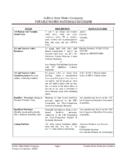
7 Bell contour shown indicates bottom of socket in a standard all bell added laying lengthA Diameter for 8 minimum length A Diameter for 5-1/2 minimum length Bottom of socket T a diameterAll sizes For 14 - 48 For 3 - 12 sizEs diMEnsions WEight Inches Inches Pounds a t Plain End 3 .48 11 4.
8 47 13 6 .50 21 8 .54 30 10 .60 41 12 .68 56 14.
9 66 63 16 .70 76 18 .75 92 20 .80 109 24 .89 145 30 208 36 279 42 361 48 458 MEchanical joint FittingsNSF Certified toANSI/NSF 61P 6866.
10 DiP . pipe 2010 EditionrEVisEd pipe and FoundrY co. MEchanical joint Fittings Bro-007Mj and Mj Mj and PEaatatsrrFor dimensions of Mechanical Joints see page dimensions of plain ends see page Bends sizE PrEssurE rating diMEnsions WEight Inches psi Inches Pounds t a s r Mj & Mj Mj & PE 30 250