Transcription of Dynamic Balancing
1 Page 1 Primer onDynamic Balancing Causes, Corrections and Consequences Presented at MainTech South 982 December 1998 ByJim LyonsInternational Sales ManagerIRD Balancing International Page 2 AbstractWhen man invented the wheel, he very quickly learned that if it wasn tcompletely round and if it didn t rotate evenly about it s central axis, thenhe had a problem!The wheel would vibrate, causing damage to itself and it s supportmechanism and in severe cases, be unusable.
2 As the task ofmanufacturing a replacement was so huge and time consuming, a methodhad to be found to minimize the problem. Research showed that the wheeland its shaft had to be in a state of balance, the mass had to be evenlydistributed about the rotating centerline so that the resultant vibration wasat a minimum. This had to be achieved during the manufacturing process(and perhaps just as importantly, as wear occurred) so that maximumservice life could be achieved from the man still suffers from the same problem only now the problem isamplified. As machines get bigger and go faster, the effect of theunbalance is much more level of unbalance that is acceptable at a low speed is completelyunacceptable at a higher speed.
3 This is because the unbalance conditionproduces centrifugal force, which increases as the speed increases. Infact, the force formula ( , page 1-6) shows that the force caused byunbalance increases by the square of the speed. If the speed is doubled,the force quadruples; if the speed is tripled the force increases by a factorof nine! It is the force that causes vibration of the bearings andsurrounding structure. Prolonged exposure to the vibration results indamage and increased downtime of the machine. Vibration can also betransmitted to adjacent machinery, affecting their accuracy and correcting the mass distribution and thus minimizing theforce and resultant vibration is the technique known as Dynamic Balancing .
4 Page 3 CausesThe International Standards Organization defines unbalance as:That condition which exists in a rotor when vibratory force or motionis imparted to its bearings as a result of centrifugal forces. ( )A more popular definition is:The uneven distribution of mass about a rotor s rotating key phrase being rotating centerline as opposed to geometriccenterline . The rotating centerline being defined as the axis about whichthe rotor would rotate if not constrained by its bearings. (Also called thePrinciple Inertia Axis or PIA). The geometric centerline being the physicalcenterline of the rotor.
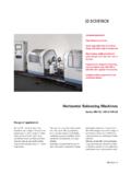
5 When the two centerlines are coincident, then therotor will be in a state of balance. When they are apart, the rotor will beunbalanced. Principal Inertia Axis CG Geometric CenterlineFig 1 Different types of unbalance can be defined by the relationship betweenthe two centerlines. These include:Static Unbalance where the PIA is displaced parallel to the geometriccenterline. (Shown above)Couple Unbalance where the PIA intersects the geometric centerline atthe center of gravity. (CG) Dynamic Unbalance where the PIA and the geometric centerline do notcoincide or most common of these is Dynamic unbalance.
6 Page 4 Manufacturing - CausesMany causes are listed as contributing to an unbalance condition,including material problems such as density, porosity, voids andblowholes. Fabrication problems such as misshapen castings, eccentricmachining and poor assembly. Distortion problems such as rotationalstresses, aerodynamics and temperature changes. Even inherent rotordesign criteria that cannot be avoided. Many of these occur duringmanufacture, others during the operational life of the machine. Whilstsome corrections for eccentricity can be counteracted by Balancing , it is acompromise.
7 Dynamic Balancing should not be a substitute for poormachining or other compromise manufacturing the manufacturing process, if proper care is taken to ensure thatcastings are sound and machining is concentric, then it follows that thetwo axis will coincide and the assembled rotor will be in a state of - CausesAs previously stated, there are many reasons why unbalance occurs whena rotor is being fabricated. Principle among these is a stack up oftolerances. When a well-balanced shaft and a well-balanced rotor areunited, the necessary assembly tolerances can permit radialdisplacement, which will produce an out of balance condition. The additionof keys and keyways adds to the problem.
8 Although an ISO standard doesexist for Shaft and Fitment Key Conventions ( ), in practice, differentmanufacturers follow their own procedures. Some use a full key, some ahalf key, and some no key at all. Thus, when a unit is assembled and thepermanent key is added, unbalance will often be the result. The modernbalancing tolerances specified by ISO, API, ANSI and others make itimperative that the conventions listed in the ISO standard be to do so will mean that the low-level balance tolerances specifiedin these standards will be impossible to achieve. Page 5 Installed Machines - CausesWhen a rotor has been in service for some time, various other factors cancontribute to the balance condition.
9 These include corrosion, wear,distortion, and deposit build up. Deposits can also break off unevenly,which can lead to severe unbalance. This particularly applies to fans,blowers, compressors and other rotating devices handling processvariables. Routine inspection and cleaning can minimize the effect, buteventually the machines will have to be removed from service unbalances will of course require large weight corrections andunless care is taken, this can have a detrimental effect on the integrity ofthe rotor. Concentrating a weight adjustment (whether adding or takingaway) at a given point can weaken the rotor. For example paper rolls arefabricated from tubing and large additions or removal of weight can effectthe strength of the walls of the roll.
10 This may cause it to deflect whenspinning at operating speed and thus induce harmful vibrations on thebearings and paper machine CausesAnother cause of unbalance that is not readily apparent, is the differencebetween types of are two distinct types - rigid and a rotor is operating within 70% - 75% of its critical speed (the speed atwhich resonance occurs, its natural frequency) it can be considered tobe a flexible rotor. If it is operating below that speed it is considered rigid rotor can be balanced at the two end planes and will stay inbalance when in service. A flexible rotor will require multi-plane a rotor is balanced on a low speed Balancing machine assuming it isrigid and then in service becomes flexible, then unbalance and thus highvibration, will be the machines, which fit this category, include steam and gas turbines,multistage centrifugal pumps, compressors and paper rolls.