Transcription of E-Series - Carling Tech
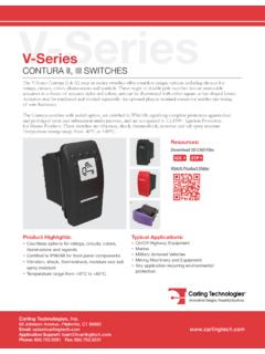
1 Carling Technologies, Johnson Avenue, Plainville, CT 06062 Email: Support: Fax: CIRCUIT BREAKERThe E-Series hydraulic-magnetic circuit breaker is ideally suited for higher current and voltage applications. It is UL listed and CSA certified for branch circuit protection, which does not require a fuse back up. It is also UL recognized and CSA certified as a supplementary protector and as a manual motor controller. Its physical features include front and back mounting, screw and stud terminals and heavy duty box wire connectors for solid wire or a pressure plate connector for standard wire. The E-Series is available with handle actuators and can be configured as .1-125 amps, up to 600 VAC or 125 VDC, with choice of time delays, actuator colors and 1 to 6 poles configuration. Additionally, a Power Selector device is also available. Product Highlights: UL listed and CSA certified Certified for circuit branch protection Recognized as a supplementary protector and as a manual motor controller Optional power selector deviceTypical Applications: High Voltage / High Current Applications Renewable Energy Military Industrial Controls GeneratorsResources:Configure a Complete PartDownload CAD & Sales DrawingEmail: Application Support: Phone: (860) 793 9281 Fax: (860) 793 9231 | E-Series Circuit Breaker General Specifications*Manufacturer reserves the right to change product specification without prior in accordance with requirements of specification MIL PRF-55629 & MIL-STD-202G as follows:Time Delay Curves62, 64 & 66(100 Amps Max.)
2 Time Delay Curves22, 24 & 26 (100 Amps Max.)Maximum Voltage 600 VAC 50/60 Hz, 125 VDC (See Table A)Current Ratings Standard current coils: , , , , , , , , , , , , , , & 100 Switch Rating SPDT; 250 VAC, 65 VDC; 80 VDC, 125 VAC (with gold contacts). Insulation Resistance Minimum of 100 Megohms at 500 Strength UL, CSA: 2200 V 50/60 Hz for one minute between all electrically isolated terminals. E-Series Circuit Breakers comply with the 8mm spacing and 3750V 50/60 Hz dielectric requirements from hazardous voltage to operator accessible surfaces, between adjacent poles and from main circuits to auxiliary circuits per Publications EN 60950 and VDE 0805. Resistance, Impedance Values from Line to Load Terminal - based on series Trip Circuit 10,000 ON-OFF operations @ 6 per minute; with rated Current and Free All E-Series Circuit Breakers will trip on overload, even when Handle is forcibly held in the ON Indication The operating Handle moves positively to the OFF position when an overload causes the breaker to of Poles 1 - 6 Mounting A 3 minimum spacing must be provided between the circuit breaker arc venting area on back connected E-Series circuit breakers and grounded obstructions.
3 E-Series circuit breakers must be mounted on a vertical , Box Type Front connected E-Series circuit breakers are supplied with box type pressure connectors that accept copper or aluminum conductors as follows: 1/0-14 Copper, 1/0-12 Circuit series and Switch Only, (with or Configuration without auxiliary switch). Shunt with current coils. Weight Approximately 252 grams/pole (Approximately 9 ounces/pole)Standard Colors Housing-Black; Actuator - See Ordering Withstands 100 Gs, 6ms, sawtooth while carrying rated current per Method 213, Test Condition I . Vibration Withstands excursion from 10-55 Hz, and 10 Gs 55-500 Hz, at rated current per Method 204C, Test Condition A. Moisture Resistance Method 106D, , ten 24-hour cycles @ + 25 C to +65 C, 80-98% Spray Method 101, Condition A (90-95% RH @ 5% NaCl Solution, 96 hrs).
4 Thermal Shock Method 107D, Condition A (Five cycles @ -55 C to +25 C to +85 C to +25 C).Operating Temperature -40 C to +85 CPulse Tolerance CurvesCURRENT (AMPS)TOLERANCE (%) - - - 35 Email: Application Support: Phone: (860) 793 9281 Fax: (860) 793 9231 | E-Series Circuit Breaker General SpecificationsElectrical TablesTable A: Lists UL Listed (489) & CSA Certified ( No. 5) configurations & performance capabilities as a Molded Case Circuit B: Lists UL Recognized & CSA Accepted configurations & performance capabilities as a Component Supplementary - 1005,00050,000125DC - 1005,00010,000125DC - 12510,000 ---12050 / - 12510,000 ---SERIES24050 / - 305,00010,00024050 / 60131 - 1005,000120 / 24050 / - 305,00010,000120 / 24050 / 60131 - 1005,000 ---120 / 24050 / 601101 - 12510,000 ---24050 / - 1005,000 --- e series TABLE A : UL489 LISTED BRANCH CIRCUIT BREAKERSVOLTAGEINTERRUPTING CAPACITY (AMPS)MAX.
5 RATINGFREQUENCYPHASEWITHOUT BACKUP FUSECIRCUIT CONFIGURATIONFULL LOAD AMPSCURRENT RATINGHIGH INTERRUPTINGCAPACITY (AMPS)125DC - 100 --- --- 5,000TC1,2, OL1, U1TC1,2, OL1, U1125DC --- ---101 - 120 ---5,000TC1,2, OL0, U1TC1,2, OL0, U1150DC --- - 125 ---5,000TC1, OL0, U3TC1, OL0, U3160DC - 100 --- ---5,000TC1,2, OL1, U1TC1,2, OL1, U1150 / 300DC - 100 --- ---5,000TC1,2, OL1, U1TC1,2, OL1, U1 series &120 / 24050 / 601 - 100 ---5,000TC1,2, OL0, U1TC1,2, OL0, U1 SHUNT24050 / - 100 --- ---5,000TC1,2, OL1, U1TC1,2, OL1, U125050 / - 100 ---10,000 ---TC1,2, OL1, C1TC1,2, OL1, C1 ---5,000TC1,2, OL1, U1TC1,2, OL1, U110,000 ---TC1,2, OL1, C1TC1,2, OL1, C148050 / 601 & - 100 ---10,000 ---TC1,2, OL1, C1TC1,2, OL1, C1480 150 / 601 & - 50 ---10,000 ---TC1,2, OL1, C1TC1,2, OL1, C160050 / 601 & - 100 ---10,000 ---TC1,2, OL1, C1TC1,2, OL1, C1600 2DC --- - 125 ---5,000TC1, OL0, U3TC1, OL0, U3125DC - 120160DC - 100 SWITCH24050 / - 100 ONLY27750 / - 10048050 / 601 & - 10060050 / 601 & - 10027750 / - 100 ---CSAWITH BACKUP FUSE3 WITHOUT BACKUP FUSEE - series TABLE B: COMPONENT SUPPLEMENTARY PROTECTORSCIRCUIT CONFIGURATIONVOLTAGECURRENT RATINGSHORT CIRCUIT CAPACITY (AMPS)APPLICATION CODESMAX.
6 RATINGFREQUENCYPHASEFULL LOAD AMPSGENERAL PURPOSE AMPSUL/CSAULN otes: 1 Per pole opposite polarity rating - Delta 4 Poles connected in series3 Requires branch circuit backup with a UL Listed Type K5 or RK5 fuse rated 15A minimum and no more than 4 times full load amp rating and not to exceed : Application Support: Phone: (860) 793 9281 Fax: (860) 793 9231 | E-Series Circuit Breaker General SpecificationsAgency CertificationsUL RecognizedUL Standard 1077UL Standard 1500UL ListedUL Standard 489 CSA AcceptedCSA CertifiedTUV CertifiedVDE CertifiedComponent Recognition Program as Protectors, Supplementary (Guide QVNU2, File E75596)Component Recognition Program as Manual Motor Controls (Guide NLRV2, File E135367)Protectors, Supplementary for Marine Electrical & Fuel Systems (Guide PEQZ2, File E75596) Ignition ProtectionCircuit Breakers, Molded Case (Guide DIVQ, File E129899)Component Supplementary Protector (Class 3215 30, File 047848 0 000)CSA Standard No.
7 235 Circuit Breaker Molded Case (Class 1432 01, File 093910), CSA Standard No. - MEN60934 under License No. R72031056 EN60934, VDE 0642 under File No. 10537 Table C: Lists UL Recognized, CSA Accepted and VDE Certified configurations and performance capabilities as a Component Supplementary D: Lists UL Recognized, CSA Accepted configurations and performance capabilities as Protectors, Supplementary for Marine Electrical and Fuel Systems (Guide PEQZ2, File E75596). Ignition Protected per UL 1500. UL Classified Small Craft Electrical Devices, Marine in accordance with ISO 8846 (Guide UZMK, File MQ1515) as Marine Supplementary RATINGVDE (Icn)CONSTRUCTION NOTES125DC - 100 --- 5,0005,000TC1,2, OL1, U1TC1,2, OL1, U11 or 2 PolesSERIES &24050 / 601 & - 100 ---5,0005,000TC1,2, OL1, U1TC1,2, OL1, U11 - 5 Poles. Up to 4 Current Poles, 1 Voltage PoleSHUNT41550 / 601 & - 10010,000 ---4,000TC1,2, OL1, C1TC1,2, OL1, C12 - 5 Poles.
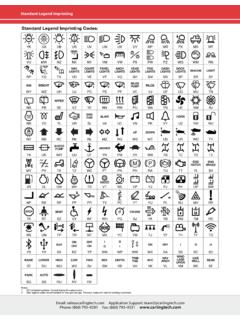
8 Up to 4 Current Poles, 1 Voltage Pole125DC - 125 SWITCH ONLY24050 / 601 & - 10041550 / 601 & - 100E - series TABLE C: COMPONENT SUPPLEMENTARY PROTECTORS WITH VDESHORT CIRCUIT CAPACITY (AMPS)WITHOUT BACKUP FUSEUL/CSAULCSAWITH BACKUP FUSE1 WITHOUT BACKUP FUSECIRCUIT CONFIGURATIONVOLTAGEAPPLICATION CODESMAX. RATINGFREQUENCYPHASEFULL LOAD AMPS65DC - 1005,000TC1,2,OL1,U1TC1,2,OL1,U1 SERIES12550 / - 1001,500TC1,2,OL1,U1TC1,2,OL1,U125050 / - 1001,500TC1,2,OL1,U1TC1,2,OL1,U1 WITHOUT BACKUP FUSEULAPPLICATION CODESE series TABLE D : UL1500 (Marine Ignition Protection)CSACIRCUIT CONFIGURATIONVOLTAGECURRENT RATINGSHORT CIRCUIT CAPACITY (AMPS)MAX. RATINGFREQUENCYPHASEFULL LOAD AMPSE lectrical TablesNotes: 1 Requires branch circuit backup with a UL LISTED Type K5 or RK5 fuse rated 15A minimum and no more than 4 times full load amp rating and not to exceed 225 : Application Support: Phone: (860) 793 9281 Fax: (860) 793 9231 | E-Series Circuit Breaker - UL 1077 Ordering Scheme1 Series2 Actuator3 Poles6 Frequency& Delay7 Current Rating8 Terminal12 AgencyApproval4 Circuit5 Auxiliary SwitchEAB01A22BC244501 SERIESE2 ACTUATORA Handle, one per pole8 TERMINAL 12 BACK CONNECTED (FRONT MOUNTED ONLY) MAX.
9 RATING1 9 10-32 Stud (All Terminals) 50 A2 9 1/4-20 Stud (All Terminals) 120 AA 9 M5 Stud (Line & Load) 50 AB 9 M6 Stud (Line & Load) 100 AFRONT CONNECTED (BACK MOUNTED ONLY) MAX. RATING3 10 Box Wire Connector (Line & Load) 100 AC 11 Box Wire Connector with Pressure Plate (Line & Load) 100 A4 10-32 Screw (Line & Load) 50 AD M5 Screw (Line & Load) 50 A5 10-32 Bus-Type Screw (Line), 10-32 Screw (Load) 50 AE M5 Bus-Type Screw (Line), 10-32 Screw (Load) 50 A6 10 10-32 Bus-Type Screw (Line), Box Wire Connector (Load) 100 AF 11 10-32 Bus-Type Screw (Line), Box Wire Connector with Pressure Plate (Load) 100 A7 1/4-20 Screw (Line & Load) 100 AG M6 Screw (Line & Load) 100 A8 1/4-20 Bus-Type Screw (Line), 1/4-20 Screw (Load) 100 AH M6 Bus-Type Screw (Line), M6 Screw (Load) 100 A9 10 1/4-20 Bus-Type Screw (Line), Box Wire Connector (Load) 100 AJ 11 1/4-20 Bus-Type Screw (Line), Box Wire Connector with Pressure Plate (Load) 100 A10 MOUNTING / BARRIERSBACK CONNECTED (FRONT MOUNTED ONLY)
10 Mounting InsertsA 6-32B ISO M3 FRONT CONNECTED (BACK MOUNTED ONLY) 14 Back Mounting Foot Type Front Mounting Inserts (Optional Use)C Short 6-32 D Short ISO M3E Long 6-32 F Long ISO M33 POLES 1 1 One2 Two3 Three4 Four5 Five6 Six4 CIRCUIT 2A 3 Switch Only (no coil)B series Trip (current)C series Trip (voltage)D Shunt Trip (current)E Shunt Trip (voltage)F Relay Trip (current)G Relay Trip (voltage)5 AUXILIARY SWITCH 40 without Auxiliary Switch 6 Terminals2 Terminals 7 Terminals3 Solder Lug (Gold Contacts)4 Terminals 8 Terminals (Gold Contacts) 9 Terminals6 FREQUENCY & DELAY 03 3 DC 50/60Hz, Switch Only 34 DC, 50/60Hz Medium10 5 DC Instantaneous 36 DC, 50/60Hz Long12 DC Short 62 50/60Hz Short, High-inrush14 DC Medium 64 50/60Hz Medium, High-inrush16 DC Long 66 50/60Hz Long, High-inrush20 5 50/60Hz Instantaneous 72 DC, Short,High-inrush22 50/60Hz Short 74 DC,Medium, High-inrush 24 50/60Hz Medium 76 DC, Long, High-inrush26 50/60Hz Long 92 6 DC, 50/60Hz Short, High-inrush30 DC, 50/60Hz Instantaneous 94 6 DC, 50/60Hz Medium, High-inrush32 DC, 50/60Hz Short 96 6 DC, 50/60Hz Long, High-inrush11 MAXIMUM APPLICATION RATING 15A 65 VDC, 120 A G 16 600 VAC, 100 AB 125 VDC, 120 A H 16 480 VAC, 100 AC 120/240 VAC, 100 A J 16 415 VAC, 100 AD 240 VAC, 100 A L 16 160 VDC, 100 AE 16 277/480 VAC, 100 A T 125 VDC/240 VAC, 100 AF 277 VAC, 100 A W 16 125 VDC/415 VAC.


![Dimensional Specifications: in. [mm] - Carling Tech](/cache/preview/2/7/7/b/1/c/c/3/thumb-277b1cc3c1030fdd5e2f38c8b7480b64.jpg)