Transcription of EBS Electronically controlled Brake system in motor coaches
1 EBSE lectronically controlledBrake systemin motor coachesSystem and functional description1. Edition Copyright WABCO 2003 Vehicle Control SystemsAn American Standard Company8150004083 The right of amendment is reservedVersion 001 of / Advantages of EBS.. structure in busesSystem structure 2- axle bus .. 4 WABCO EBS construction kit .. 5 system variants .. 6 Wiring diagram 2- axle bus ..7 Wiring diagram 3- axle bus .. of componentsBrake signal transmitter 480 00.. 0 .. 9 EBS central module 446 135 .. 0 .. 10 Proportional relay valve 480 202 .. 0 .. 113/2 relay valve 480 205 .. 0 ..12 axle modulator 480 103 .. 0 .. of EBS functionFunction of the electro-pneumatic unit .. 14 Function of pneumatic redundancy.. 14 Additional redundancy on the front axle .. 14 Rear axle redundancy..15 Electrical / electronic structure.
2 15 Control functions .. 16 Backup functions .. 17 Halt Brake , Brake hold and release aid .. recognition and display Error recognition .. 18 Error display .. emergency modes / EBS test types .. PC - Diagnosis.. 21 Diagnostic equipment for WABCO EBS .. 22 Diagnostic Software EBS Euro .. SettingParameter setting .. 303 EBSI ntroductionThe demands made on braking systems are increasingsteadily. Therefore, the development and introduction ofan electronic braking system (EBS) is a logical increases traffic safety through reduced stoppingdistance and improved Brake stability. The full diagnosisand surveillance functions as well as the display of brakelining wear offer an effective fleet of EBSEBS reduces service costs considerably. The electronic braking system has a lot offunctions.
3 The aim is to maximise braking safety atreduced costs, for instance by optimising wheelbrake lining wear. Setting pressure, according to wear criteria, to thefront and rear axle results in uniform lining wear is minimised by making the load on allwheel brakes uniform. Moreover, servicing andlining replacement are done at the same time. Thisreduces down-time costs. Depending on the vehicle utilisation profile andother factors, this also means considerable savingsfor the vehicle user. In terms of wheel Brake servicecosts alone, a firsthand owner will save moremoney with an Electronically braked bus than witha vehicle with a conventional braking Brake safetyWABCO did not only take existing regulations intoconsideration while developing EBS. Top priority wasgiven to safety and user advantages.
4 This is why avehicle with EBS can clearly do more than is required high safety quality attributed to EBS is due toseveral factors: Braking time is reduced through shorter responsetime and pressure build-up time of the brakes onthe front and rear axle (s). The improved ABS function increases vehiclestability when brakes are activated. The components of the front and rear axle brakingsystem and Brake lining wear are monitoredpermanently. The integrated ASR function also providesoptimum vehicle stability and traction during startand / Advantages of :EBS components:1 EBS central module2 Brake signal transmitter3 Proportional relay valve4 ABS solenoid valve5 axle modulator63/2 relay valve7 ABS sensorsOther components:8 Compressor9 Air dryer10 Four-circuit protection valve11 Air reservoir12 Hand Brake valve13 Relay valve FBA14 Brake cylinderSystem structure in braking system for buses with no attachment (4S/4M system )12345678910111213145 EBSWABCO EBS construction kitThe design and structure of WABCO EBS allow highflexibility for vehicle manufacturers during systemconstruction.
5 In terms of range subsystem or full system addition and cut-off redundancy electrical interfaces the most complex demands can, therefore, be met. Tomeet the vital needs of the vehicle owner, WABCO recommends an EBS with an individual pressure controlunit on the front and rear axle , and which provides forpneumatic redundancies in all Brake structure in EBS described here consists of a dual-circuit, purelypneumatic unit and a superimposed single-circuit,electro-pneumatic unit. This configuration is describedas 2P/1E system . The single-circuit, electro-pneumatic unit comprises acentral electronic control device (central module), theaxle modulator with integrated electronic unit for the rearaxle, and, if necessary, the axle modulator for the thirdaxle, a Brake signal transmitter with two integrateddesired value sensors and Brake switches, as well as aproportional relay valve and two ABS valves for the frontaxle.
6 In terms of structure, the dual-circuit pneumatic unitbasically corresponds to that of a conventional brakingsystem. This unit serves as redundancy and onlybecomes active in case of electro-pneumatic circuitfailure. 2P/1E-EBSAME= axle modulatorBWG= Brake signal transmitterECAS = Electronically Air Suspension SystemEMR= Electronically engine controlPRV= Proportional relay valveREDV = 3/2 relay valve (redundancy valve)RET= RetarderRV= Relay valveS= Speed sensorV= Wear indicatorBatteryhalt brakesupplythird axle6 EBSEBS 4S/4M in buses with optional trailer control system structure in 6S/6M in articulated buses 446 130 XXX 0 III I II II II IIIEP B 4S /4M RetarderMotorFahrzeugdatenbus SAE J 1939 GetriebeNiveau-regelung1 Zentralsteuerger t EBS2 Bremswertgeber3 Prop.
7 Relaisventil4 ABS Magnetregelventil5 Achsmodulator6 redundanzventil7 Splus Stabsensoren8 Verschlei sensoren9 Relaisventil 787878781234565978784 OptionalRedundancy valve1 Central control unit EBS2 Brake signal transmitter3 Proportional Relay valve4 ABS Solenoid Control valve5 axle modulator9 Relay valve7 Splus rod sensor8 Wear indicators6 3/2 relay valve (redundancy valve)EngineGearboxLevel controlvehicle data bus SAE J 1939 RetarderAnh nger-steuerventil 446 130 XXX 0 III I II IIII IIIEP B 4S/4M Luftbeh lterRetarderMotorFahrzeugdatenbus SAE J 1939 GetriebeNiveau-regelung1 Zentralsteuerger t EBS2 Bremswertgeber3 Prop. Relaisventil4 ABS Magnetregelventil5 Achsmodulator6 Anh ngersteuerventil7 Splus Stabsensoren8 Verschlei sensoren9 Redundanzventil 7878787861234459 ISO 11992 ISO 7638 EngineGearboxLevel controlvehicle data bus SAE J 1939air reservoirtrailer control valve1 Central control unit EBS2 Brake signal transmitter3 Proportional Relay valve4 ABS Solenoid Control valve5 axle modulator6 Trailer control valve7 Splus rod sensor8 Wear indicators9 3/2 relay valve (redundancy valve)Retarder7 EBSS ystem structure in busesWiring diagram 841 801 701 0: Dual- axle bus (4S/4M) structure in busesWiring diagram 841 801 702 0: Three- axle bus (6S/6M) signal transmitter 480 001/ 002.
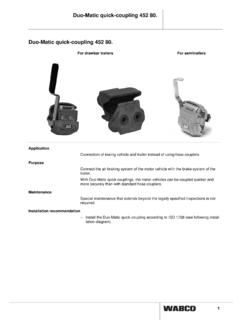
8 0 The Brake signal transmitter is used to produce electricaland pneumatic signals, and to increase and decreasethe air pressure of the Electronically controlled brakingsystem. The device has a dual-circuit pneumatic and adual-circuit electrical structure. Actuation start is record-ed Electronically by a double switch. The operating tap-pet s route is controlled and transmitted as pulse-widthmodulated electrical signal. Further pneumatic redun-dancy pressure is delivered in circuits 1 and 2. Thepressure in the second circuit is retained slightly in theprocess. In case of (electrical or pneumatic) failure of acircuit, the other circuits remain on bus type, the Brake signal transmitter isactuated via a running plate (480 002 .. 0) 0) or via apush pedal using the tappet (480 001.
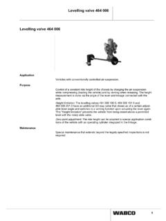
9 0).How it works:Description of central module 446 135 .. 0 The central module is used to control and monitor theelectronically controlled braking system . It determinesthe vehicle s nominal delay from the signals received bythe Brake signal transmitter. The nominal delay and thewheel velocity measured by the speed sensors are inputsignal for the electro-pneumatic control unit, which usesit to calculate nominal pressure values for the front axleand rear axle (s). The front axle s nominal pressure valueis then compared with the measured actual value, andany existing deviations corrected with the help of theproportional relay valve. Moreover, the wheel velocity isevaluated so that in case of locking, an ABS control canbe carried out by modulating the braking pressure in thebrake cylinders.
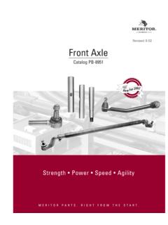
10 The central module exchanges EBSsystem bus related data with the axle modulators. The central module communicates with other systems(engine control unit, retarder, display unit, etc.) via thevehicle data bus in accordance with SAE J central unit:Description of relay valve 480 202 .. 0 The proportional relay valve is used in the electronicallycontrolled braking system to modulate the brakingpressure on the front comprises the proportional solenoid valve, relay valveand pressure sensor. Electrical drive and monitoringtakes place via the central module of the hybrid system (electro-pneumatically / pneumatically).The control current impressed by the electronic unit istransformed via the proportional solenoid valve into acontrol pressure for the relay valve.