Transcription of ECAC LIBRARY - Defense Technical Information …
1 ECAC-CR-83-200 Cy. :DEPARTMENT OF DEFENSEQ Electromagnetic Compatibility Analysis CenterAnnapolis, Maryland 21402 field ANTENNA HANDBOOK Pieparad forJoint Chiefs of StaffJUNE 1984 CONSULTING REPORTP repared byJames A. KuchtiT Research histitutetinder Contract toDepartment of DefenseApproved for public release; distribution LIBRARYYou are persoiw, IU Fc'-oat~ tot thisbook. O0 NO1 tianster this boua to anoL,4 -5 08 'person without permission ol the fibrary v " ; ,, -' "- -.'--- , , '"- -= ; " - -' "%ECAC-CR-83-200 This report was prepared by the IXT Research Institute as part of AFProject 649E under Contract F-19628-80-C-0042 with the Electronic SystemsDiVision of the Air Force Systems Command in support of the DoDElectromagnetic Compatibility Analysis Center, Annapolis, report has been reviewed and cleared for open publication and/orpublic release by the appropriate Office of Information (01) in accordancewith AFR 190-17 and DoDD There is no objection to unlimiteddistribution of this report to the public at large, or by DTIC to the NationalTechnical Information Service (NTIS).
2 " /- e, !eviewed by-JAIES L. SMALLP roject Manager, IITRI Director of ResearchContractor OperationsApproved byCHlARLES L. FLYNN, CoIe ,oSAF 3. , USMCDD irector Marine Corps Deputy DirectorSnWIC[Aiss!iNSECURITY CLASS'FICATION OF THIS PAGE .n Da* Ente.,.ed)REPORT DOCUMENTTIONINSTRUCTIONSREPORT__ DOCUMENTATIONPAGE_ BEFORE COMPLETING FORMI. REPORT NUMSER -i. GOVT ACCESSION NO: I. RECIPIENT'S CATALOG NUMBERECAC-CR-83-2004. TITLE (and Subtitle) S. TYPE OF REPORT II PERIOD COVEREDFIELD ANTr-NNA XMDIOOK CONSULTINGG. PERFORMING ORG. REPORT NUMBER7. AUTMO'(s) S. CONTRACT OR GRANT NUNMER(*)r *Jamias A. Kucb F-19628-80-C-0042I! _CDRL # lOPI,. PERFORkmIOAG C'.AHIZATION NAMF 'NO ADDRESS 10. PROGRAM ELEMENT. PROJECT, TASKDolt) E.!ctromanetJc Compatibility Analysis Center AREA 6 WORK UNIT NUMBERSN orth Severn P0553 Annapolis, D 214U211. CCNTROLLING OFFICE NAME AND AODRESS 12. REPORT DATEJUNE 1984 Joint Chiefs of Staff IS. NUNSER OF PAGES98A4. MONITORING AGENCY NAME I ADORESS(i1 different 1,- Cont o 4in Office) it.]
3 SECURITY CLASS. (of this tepot)|$e DE tA$$IFWCA|N/OOWNG tADIN G%CwEDULE1S. DISTRIBUTION STATEMENT (of thie Report)Approved for public release; distribution DIST RISUTION STATEMENT (.1 &.ettct .e*.ed in Block 20. Ii di t Report)II. SUPPLEMENTARY NOTES13 KEY WORDS (CoAItimm an to~** aOd. It o%** 14it Ay blok kMi&ANTENNASHIGH FREQUENCYPROPAGATIONVERY HIGH FREQUNCY10 ASSTRACT (C~tinua .t N aide If A4ceseeld ttqr by StackThis handbook presents basic propagation theory, the fundamentalsconcerning antennas, and the design and use of tactical hiqh frequency andvery high fvtquency antennas. It is a field reference for basic antenna facts* and a usage guide for JAO t 1413 9 OiTIOM OF I NOV &S IS OBSOLETESECURITY CLASIIFICATION Of ThIS PAGE (Ifto DOata Eatek'd).. -.., .-, .-, i. ".y- ~ .. r:..- -. - TABLE OF CONTENTST itle PageINTRODUCTION ..SECTTJN IHF AND VHF PROPAGATION FUNDAMENTALSHIGH FREQUENCY COMMUNICATIONS (2 TO 30 MHz).. 3"Ground-Wave Propagation 3 Sky-Wave Propagation.))
4 4 VERY HIGH FREQUENCY COMMUNICATIONS (30 TO 88 MHz) .. 8 SECTION IIANTENNA FUNDAMENTALS* WAVELENGTH AND FREQUENCY .. 11"RESONANCE ..* * * 9**..* ..* 13 REFLECTIONS ..13, -GAIN15 STAKE-OFF ANGLE ..s*. 15ij' PATTERNS ..16*i SECTION IIIHF ANTENNAS* GENERAL .. 21*- DETERMINING ANTENNA GAIN .. 24"ANTENNA SELECTION PROCEDURE .. Procedures .. 25"Example .. 25, AS-2259/AS-2263 .. 27 TABLE OF CONTENTS (Continued)SECTION III (Continued)Title PageOE-85/OE-86 .. 29* VERTICAL WHIP .. 31S~HALF-wAVE .. 35 INVERTED VEE .. 41,* LONG WIRE .. 76, SLOPING VEE .. 49i3 SLOPING WIRE ..52* VERTICAL HALF .. 7 SECTION IVE DVHF ANTENNASGEPAIER O RKAL .N .. 69RC-292 .. 66OE-254 .. 8AS-2236 ..* .. 72 VERTICAL HALF RLHOMBICiOE-303 .. 75 SECTION VEXPEDIENT TECHNIQUESREPAIR OF BROKEN ANTENNAS .. 79 INSULATORS ..80 SUPPORTS .. 80 TERM NATIG RE IST RS ..t .. OF CONTENTS (Continued)-. SECTION V (Continued)Title PageE~. XPEDI ENT WIRE ..82,..GROUNDING ..SECTION VI" FOR MORE Information .
5 85V/via,'INTRODUCTION"Of all the variables affecting communications, the onefactor that the individual o-erator has the most control over isthe antenna and its use. By using the proper antenna, anop -ator may change a marginal circuit into a reliable handbook presents basic propagation theory, the fundamentals* of antennas, and the design and use of tactical high frequencyand very high frequency antennas. A working knowledge of this"handbook will allow the operator to properly select and employindividual antennas to provide the strongest possible signal atthe receiving station of his circuit. This handbook is notintended to be a Technical handbook on antennas, but is intendedto be a field reference for basic antenna facts and a usage guidefor I and II present Information which should beunuerstood by radio operators, however, this handbook can be usedwithout thorough knowledge of those sections. Section IIAcontains HF antenna selection procedures and describes the morecommon tactical HF antennas.
6 Section IV does the same for VHFantennas. Section V presents info>rmation on making antennasusing field available materials. Section VI lists publicationsavailable from the different services that give detailedinformation on piopagation and IHF AND VHF PROPAGATION FUNDAMENTALSP ropagation is the process by which a radio signal travelsthrough the atmosphere from one antenna to another. This sectionbriefly describes the propagation factors that need to be knownto better understand the antenna Information presented in thefollowing sections. This section is divided into two majorparts, high frequency (HF) propagation and very high frequency(VHF) propagation. Each part can stand alone so that the radiooperator interested in only HF or VHF communications can godirectly to that FREQUENCY COMMUNICATIONS (2 TO 30 MHz)High frequency communications is accomplished by eitherground-wave or sky-wave propagation. With current low-poweredman-pack radios, ground-wave communications can be establishedout to 20 to 30 kilometers (kin).
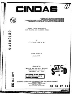
7 High powered equipment (mountedin jeeps and vans) can extend that range to approximately 80 to100 km. The coverage from sky-wave communications, on the otherhand, can vary from several kilometers to thousands PropagationGround-wave propagation involves the transmission of a radiosignal along or near the surface of the earth. The ground-wavesignal is divided into three parts: the direct wave, thereflected wave, and the surface direct wave travels through the atmosphere from oneantenna to the other in what is called the line-of-sight (LOS)mode. Maximum LOS distance is dependent on the height of anantenna above the ground; the higher the antenna the further themaximum LOS distance. Because the radio signal travels in air,any obsttuctions, such as a mountain, between the two antennascan block or reduce the signal and prevent communications. Foran antenna 10 feet above the earth, a maximum LOS distance ofabout to 8 km (4 to 5 miles) can be reflected wave, like the direct wave, travels throughthe atmosphere but reflects off the earth in going from thetransmitting antenna to the receiving antenna.
8 Together, thereflected wave and the direct wave are called the space PACE WAVESTR~iMUMMATE DI CECT WAVE RCIE"SURFACE WAVE ALONG SURFACEC omponents of ground wave."The third part of a ground wave is the surface wave. Thispart travels along the surface of the earth and is the usualmeans of ground-wave communication. The surface wave is verydependent on the type of surface between the two antennas. Witha good conducting surface, such as sea water, long ground-wavedistances are possible. If there is a poor surface between the"antennas, such as sand or frozen ground, the distance expectedfor the surface wave is small. The surface wave range can alsobe reduced by heavy vegetation or mountainous PropagationBeyond the range covered by the ground-wave signal, HFcommunications are possible through sky-wave propagation. Sky-wave propagation is possible because of the bending of the radio"signal by a region of the atmosphere called the ionosphere is an electrically charged (ionized) regionof the atmosphere that extends from about 60 km (37 miles) to1000 k- (620 miles) above the earth's surface.
9 The ionizationresults from energy from the sun and causes radio signals toreturn to earth. Although the ionosphere exists up to 1000 km,the area important for HF communications io below about 500 area is divided up into four regions: D, E, F1, and D region is closest to earth and only exists during thedaylight hours. It does not have the capability to bend a radiosignal back to earth but it does play an important role in HFcommunications. The D region absorbs energy from t',e radiosignal passing through it thereby reducing the strength E region, the next higher region, is present 24 hours aday, although during night hou's it is much weaker thaii duringthe doy. The E region is the rfirst region with enough charge tobend radio signals. At times, parts of the E region becomehighly charged and can either help or block out HFcommunications. These highly charged areas are called Sporadic Eand occur most often during the of60 thKM oahieThe Wost ipCrtn rein orH22ouuialn aete~~~nd~~ F2re ions.
10 Temjrt fH kw omnctosdpnThe bendingcofra rdofsgalb the ionosphphdepnd oThhfeqenc ofs irrthe radionsinl the dere of mniaioniaretion intheF io giosnhre ndThe manorit af wHic thw e cadommniaional dependonthenshe Aihth 2 vertica (btringh up)anle the highestlontefrequency ohf wil. radi beignac, tthe isegreed the crnizticalifrequency. Each region of the (E. Fl, F211 will have aseparate critical frequency. Foz a vertical angle, signals abovethe highest critical frequency will pass all ionosphericrogions and on into outer space. Frequencies below the of a region will be back to the earth by thatregion; however, if the frequency is too low, the signal will beabsorbed by the D region. In order to have HF sky-wave5communications, a radio signal must be a high enough frequency toT, pass through the D region but not too high a frequency so that itdoes not pass through the reflecting angle at which a radio signal strikes the ionosphereplays an important part in sky-wave communications.)