Transcription of EcoSystem Dimming Power Module for 3-wire …
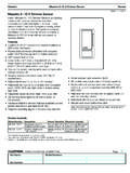
1 Job Name:Job Number:Model Numbers:Page SPECIFICATION SUBMITTAL369617c 1 Dimming ModuleC5-BMJ-16 AEcoSystem EcoSystem Dimming Power Module for 3-wire Lutron Dimming BallastsThe Lutron EcoSystem Dimming Power Module allows integration of Lutron 3-wire phase controlled Dimming ballasts into Lutron EcoSystem bus supplies (Eco-10 and Hi-lume series only). The Power Module combines digital commands and sensor data to determine the proper light Continuous, flicker-free Dimming from 100% to minimum ballast level. (10% for Eco-10, 5% for Hi-lume Compact SET, 1% for Hi-lume) Provides 20 V- Power for and responds to one occupancy sensor, one EcoSystem daylight sensor, and one EcoSystem personal control input (infrared receiver or wallstation) Communicates status and sensor levels over the EcoSystem bus supply Works with the PHPM Power interface.
2 Note: C5-BMJ-16A must be powered from a 120 V~ distribution panel. See page 5 in this document for details. Universal voltage input: 100 277 V~ 50/60 Hz Non-volatile (EEPROM) memory stores specific system information for 10 years from Power down to Power restored 100% performance tested at factoryE1E2+20 VCommonIROCCD aylightE1E2 Class 2 SensorsCapteurs Classe 2 Sensores Clase 2 Class 2 LinkLien Classe 2 Enlace Clase 2 EcoSystemTMMultiple Fixture Dimming ControlContr le de gradation de multiples luminairesControl atenuador de m ltiples l mparasPWRSTATI ndicateur de puissance (PWR)On: l unit est aliment eOff: l unit n est pas aliment e ou est dysfonctionnelleIndicateur d activit (STAT)Plein: Niveau de circuit Impulsion: Aucune communicationPower Indicator (PWR)On.
3 Unit is poweredOff: Unit is not powered or is malfunctioningStatus Indicator (STAT)Solid: Circuit LevelPulse: No communicationIndicador de Alimentaci n (PWR)Encendido: unidad tiene corrienteApagado: unidad no tiene corriente o no est funcionando correctamenteIndicador de estado (STAT)S lido: Nivel del CircuitoPulsante: No hay comunicaci n C5-BMJ-16 ACOMDYLTP/N 500-10755 12345678 KeypadEcoSystem Bus SupplyEcoSystem BallastLighting RemoteOccupant SensorEcoSystem One-LineDaylight SensorEcoSystem BallastEcoSystem BallastEcoSystem Dimming Power ModuleEco10 or Hi-lume Ballast*Energi Savr Node unit*IR ReceiverTo additional ballasts and modules (up to 64 total)* Does not count as one of the ballasts or modules on the EcoSystem Bus.
4 Job Name:Job Number:Model Numbers:Page SPECIFICATION SUBMITTAL369617c 2 Dimming ModuleC5-BMJ-16 AEcoSystemSpecifications Standards UL 916 Listed CSA 184 Certified NOM California Energy Commission (CEC) Listed Meets ANSI Category A surge protection standards up to and including 6 kV Manufacturing facilities employ ESD reduction practices that comply with the requirements of ANSI / ESD Lutron Quality Systems registered to ISO Complies with requirements for use in other spaces used for environmental air (plenums) per NEC 2014 (C)(3) M eets the Canadian National Building Code plenum requirements for a concealed space used as a plenum within a floor or roof assembly F or commercial use, Class A onlyPower Operating Voltage: 100 277 V~ 50/60 Hz Dimming Range: 100% to minimum ballast relative light output level (10% for Eco-10, 5% for Hi-lume Compact SET, 1% for Hi-lume) Switched Output Rating: 16 A Softswitch load Control Output Rating: 500 mA for use with Lutron 3-wire ballasts or Lutron interface device IEC PELV/NEC Class 2 Sensor Power .
5 20 V-, 50 mA Load Types Lutron 3-wire phase controlled fluorescent Dimming ballasts (Eco-10 and Hi-lume)Dimmable Load Types Requiring an Interface EcoSystem 16 A Module can dim additional loads other than Hi-lume and Eco-10 ballasts when the appropriate Lutron PHPM-WBX models (PHPM-WBX-120-WH and PHPM-WBX-DV-WH) are used. Note: C5-BMJ-16A must be powered from a 120 V~ distribution panel. See page 5 of this document for details. Additional load types are as follows: Incandescent Halogen MLV ELV (must be manufacturer approved for reverse phase control) Neon / Cold Cathode Lutron Tu-Wire Fluorescent Dimming BallastEnvironment Ambient Temperature Operating Range: 32 F to 104 F (0 C to 40 C) Relative humidity: less than 90% non-condensing For indoor use onlyModule Wiring Terminal blocks accept wires of the following size: EcoSystem bus (E1, E2): 22 AWG to 12 AWG ( m m2 to 4.)
6 0 mm2) solid wire IEC PELV/NEC Class 2 Sensors: 22 AWG to 12 AWG ( m m2 to 4 .0 mm2) solid wire Wiring between Module and ballasts is 4 conductors: Switched Hot Dimmed Hot Neutral Ground Wiring between Module and ballast shall not exceed 500 ft (150 m) Wiring between Module and sensors shall not exceed manufacturers specifications. Job Name:Job Number:Model Numbers:Page SPECIFICATION SUBMITTAL369617c 3 Dimming ModuleC5-BMJ-16 AEcoSystemDimensions A = in (200 mm) B = in (130 mm) C = in (65 mm) DimensionsCABC5-BMJ-16AC5-BMJ-16 AJunction boxCEILINGWALL Mounting Mount the EcoSystem Power Module onto a 4 in x 4 in (102 mm x 102 mm) standard junction box (not included, but available; Lutron P/N 241496 Mount on a vertical or horizontal surface; all Power wire connections will be made in the junction box; all EcoSystem bus wiring (Class 1 or IEC PELV/NEC Class 2) and sensor wiring (IEC PELV/NEC Class 2 only) connections will be made within the front cover of the unit.
7 Mount in a location where the PWR and STAT indicators are Contractors and Engineers All field installed IEC PELV/NEC Class 2 wiring must be separated from line voltage wiring by at least in ( mm) Some local electrical codes require IEC PELV/NEC Class 2 wiring to be separately routed in a metal conduit Job Name:Job Number:Model Numbers:Page SPECIFICATION SUBMITTAL369617c 4 Dimming ModuleC5-BMJ-16 AEcoSystem Connect the input feed wires and the output load wires to the Module as indicated in the wiring diagrams below Wiring between Module and ballasts shall not exceed 500 ft (150 m) Wiring to Lutron 3-wire Dimming Ballast:E1E1+20 VCommonIROCCD aylightE2E2 Class 2 SensorsCapteurs Classe 2 Sensores Clase 2 Class 2 LinkLien Classe 2 Enlace Clase 2 EcoSystem Multiple Fixture Dimming ControlContr le de gradation de multiples luminairesControl atenuador de m ltiples l mparasPWRSTATI ndicateur de puissance (PWR)On: l unit est aliment eOff: l unit n est pas aliment e ou est dysfonctionnelleIndicateur d activit (STAT)Plein: Niveau de circuit Impulsion: Aucune communicationPower Indicator (PWR)On: Unit is poweredOff: Unit is not powered or is malfunctioningStatus Indicator (STAT)Solid: Circuit LevelPulse: No communicationIndicador de Alimentaci n (PWR)Encendido.
8 Unidad tiene corrienteApagado: unidad no tiene corriente o no est funcionando correctamenteIndicador de estado (STAT)S lido: Nivel del CircuitoPulsante: No hay comunicaci n C5-BMJ-16 ACOMDYLTP/N 500-10755 Distribution PanelLutron 3-wire Phase-Control Dimming BallastLutron 3-wire Phase-Control Dimming BallastFixture GroundFixture GroundGreenWhiteBlackGreen (ground)White (neutral)Red (switched hot)GreenWhiteBlackGroundNeutralLine / HotC5-BMJ-16 AEcoSystem Power ModuleGreenWhiteRedBlackOrange (dimmed hot)OrangeGreenWhiteBlackOrangeOrangeWir ingEcoSystem Power Module Line Voltage WiringColors indicate the Module and ballast wire colors and/or ballast terminal colors Job Name:Job Number:Model Numbers.
9 Page SPECIFICATION SUBMITTAL369617c 5 Dimming ModuleC5-BMJ-16 AEcoSystemL/HNDHL/HNNB lack (L/H)Orange (DH)White (N)LoadControl NeutralC5-BMJG reenRed (cap off)Distribution Panel*(120 V~ only)Load breakerLoad wiring 1*Note: C5-BMJ must be powered from a 120 V~ distribution panel to ensure proper voltage to the Zone In terminal of the PHPM-WBX in120 V~Only1 Load feed: 120 V~ for PHPM-WBX-120-WH; 120 277 V~ for PHPM-WBX-DV-WHLegendL /H Line / HotN NeutralSH Switched HotDH Dimmed Hot Ground Not UsedWiring (continued)Wiring to an EcoSystem C5-BMJ Interface - Separate Power Feeds for Control and Load SidesControl side must be 120 V~The load breaker may be on a different phase than the control breaker.
10 Job Name:Job Number:Model Numbers:Page SPECIFICATION SUBMITTAL369617c 6 Dimming ModuleC5-BMJ-16 AEcoSystem Wire the EcoSystem bus to E1 and E2 terminals on the front of the Module . When the EcoSystem bus is wired Class 1, the bus wiring must enter the left side knock out and maintain in (6 mm) spacing from the IEC PELV / NEC Class 2 sensor wiring. When the EcoSystem bus is wired IEC PELV /NEC Class 2, the bus wiring may enter either knock out on the low voltage wiring +20 VCommonIROCCD aylightE2E2E1E1+20 VCommonIROCCD aylightE2E2 Class 2 SensorsCapteurs Classe 2 Sensores Clase 2 Class 2 LinkLien Classe 2 Enlace Clase 2 EcoSystemRMultiple Fixture Dimming ControlContr le de gradation de multiples luminairesControl atenuador de m ltiples l mparasPWRSTATI ndicateur de puissance (PWR)On: l unit est aliment eOff: l unit n est pas aliment e ou est dysfonctionnelleIndicateur d activit (STAT)Plein: Niveau de circuit Impulsion: Aucune communicationPower Indicator (PWR)On: Unit is poweredOff.
