Transcription of Electric Duct Heaters - Greenheck Fan
1 1 Electric duct HeatersIDHB & IDHC SeriesMay20142 Greenheck duct Heaters are used in forced air applications to provide dedicated space heat or to supplement existing heating systems. Typical applications are: Space heating Primary heating Secondary and/or auxiliary heating Reheat Multi-zone and VAV systems ReplacementGreenheck offers two heater styles: IDHB and IDHC series. All Heaters are factory assembled and wired for 50/60 models feature: Fan interlock Ground lugs Automatic limit switch for primary over temperature protection Manual reset limit switch for secondary over temperature protection Disconnecting contactor Power terminal board control panel constructed of heavy gauge corrosion resistant steel control terminal board Left hand offset control box (standard) control components secured to a raised plate UL 1996 Listed 105 C appliance wireIDHB SeriesDuct HeatersIDHC Series Applications Models: IDHB & IDHCG reenheck has a complete line of configurable Electric duct Heaters that are perfectly suited to your HVAC application.
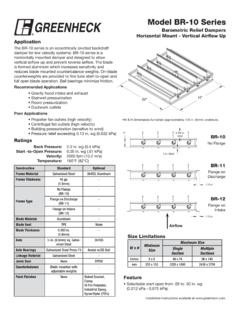
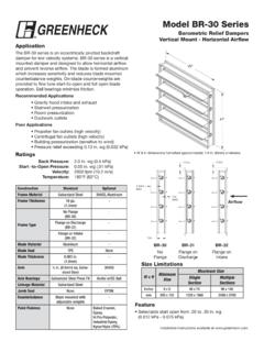
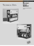
2 Our CAPS configuration tool helps you save time with its industry leading selection speed and information packed submittals. With quick lead times and a proven history of on time shipping, we can ensure that your heater will be available when you need it. Experience the difference by choosing Greenheck duct Heaters for your provide: Bi-directional airflow in horizontally mounted applications Hinged access cover with latch All limit controls are resettable Proven wire rack system provides very low pressure drop and extended element life Zero clearance rating for installations into ducts All components (except the SCR) are mounted inside the control panelIDHBIDHCV oltages/Stages120/1 - 480/3 120/1 - 575 - kW - 500 kWMinimum Size8 x 88 x 8 Maximum Size36 x 36120 x 144 Controls1 or 2 stagePneumaticStageStepSCR controlVernier SCR (Larger kW)PneumaticThermostatRoomRoomDuctTwo frame types are available: Slip in - allows you to slip the heater into the opening in the ductwork.
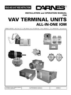
3 Flange - allows you to bolt into place between two sections of flanged inHeatingElementsWrapperTerminal orControl BoxFlangeHeatingElementsWrapperDoubleLip Terminal orControl Box Why would I choose Greenheck Heaters versus other brands?IDHB & IDHC4 Options/AccessoriesControl Panel Removable hinged access door with latch (standard) Detailed wiring diagram Configurable with left or right offsetAvailable options: Dust tight construction with gasketed cover and sealed seams Vapor barrier Recess for internally insulated ducts Flush mount configurationUL and NEC codes require Heaters in excess of 48 amps be subdivided into circuits of 48 amps or less. If 48 amps or greater, fusing comes standard. Less than 48 amps, fusing is - Power FusingA door interlocking disconnect switch is used to prevent the control door from being opened until power to the heater is - Disconnect SwitchTerminal blocks are standard on all Heaters for quick and easy integration with field installed control - Terminal BlocksDisconnecting contactors break all ungrounded lines on UL listed duct Heaters and are UL approved for 250,000 cycles.
4 There are two types available: Magnetic - standard for all Heaters Mercury - used where silent operation and/or frequent cycling is desired (optional)5 - Contactors 7 81 - Airflow SwitchFan Interlock switch (standard/UL required)Optional airflow switch senses air pressure across the heater surface closing the electrical switch and allowing the heater to activate. This switch is available with fixed or adjustable set transformers are used to provide single point wiring when the control voltage differs from the line voltage. The transformer is available as fused or unfused. 6 - control TransformerStaged ControlOne to four stages are provided controls allow a pneumatic building control system to operate Heaters with up to three stages. An airflow switch is standard with this ControlsModel IDHC is available with the following proportional control options which are compatible with a 0-10 Vdc or 4-20mA analog signal from a BMS, Room or duct Step ControllerAn electronic step controller provides electronic sequencing control of an Electric duct heater up to 12 steps.
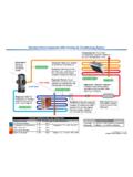
5 When interruption of power occurs all stages cycle off. Upon restoration of power the step sequence (pictured)Solid state relays are used to provide continuous modulation. SCR is the most precise form of heater SCR (Step and SCR)Vernier SCR control combines the benefits of Step and SCR control to provide precise proportional control on Heaters in excess of 135 amps. 7 - Capacity Controls 1 2 3 4 6 5 Standard heater elements are 60% Ni grade C wire which exhibit excellent performance in standard applications. Elements are supported with a wire rack system that significantly reduces element sag and pressure drop. Optional features include: 80/20 NiCr, grade A element wire provides superior corrosion resistance in reheat and high humidity applications Derated coils aid in longer element life in single and multi-zone air handler applications 8 - Elements6 Heater Selection This diagram shows typical information that you will need when selecting a duct LightPilot lights are installed on the side panel and used to indicate heater conditions as follows: - heater energized - step energized - airflow switch open Available with 24V or 120V control voltagesTime Delay RelayA time delay relay provides a delay of 30 to 60 seconds when energizing or de-energizing the circuit controlled.
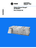
6 Standard control voltages are 24V through 277 VPressure Electric Switches (PE)A PE switch is used to control the heater with a pneumatic air signal. Requires field adjustment for specific job requirementsThermostatRoom stat - Controls heater to maintain adjustable space temperature when heater is used as primary heating methodDuct stat - Controls heater to maintain adjustable discharge temperature. This is the preferred method of control for preheat and reheat applications. This option is only available with SCR, Vernier SCR, or Step controller Width HeightMounting Type Slip-in FlangedCapacity (kW) Given or CalculatedOptions71,4004,0006,0008,00010 ,00012,00014,00016,00018,00020,000 WATTS PER SQUARE FOOT, duct AREA22,000 Velocity (fpm)2,0001,2001,000800600400200 BELOW 78 F INLET AIR78 TO 90 F INLET AIR91 TO 110 F INLET AIRM inimum Air VelocitiesGeneralA.
7 The minimum airflow through a duct heater is directly related to the inlet air temperature. Consideration must be given to both airflow across the heater and the inlet temperature. B. To calculate the watts per sq. ft. (square foot) of duct area, divide the total watts required by the duct size (Watt density = watts/ duct area (ft2). Example: duct size equal 2 ft. x 3 ft., total watts equal 20,000 watts per sq. ft. 20,000 = 3333 6C. If airflow in the duct is expressed in FPM, then a direct cross reference can be made by comparing the temperature of the air (as it enters the duct heater) to the kW rating on the table at the rated air velocity. 1. Draw a line horizontally from the watts per sq. ft required to the inlet air temperature being used. 2. From this point of intersection on the inlet temperature line, draw a line down vertically to establish the air velocity.)
8 3. In cases where the velocity is less than that determined from the chart, then the velocity must be increased, the kW required must be reduced, or both must be In cases where the airflow is expressed in CFM, convert to FPM by dividing the CFM by the duct area. CFM = FPM duct Area(ft2)Performance 400 600 800 1,000 1,200 1,400 1,600 1,800 2,000 2,200 4321 Air Velocity - FPM1, 2, 3 and 4 - the number of rows of heater the number of rows of heater coils is unknown, assume Pressure Drop - inches of water ( )Pressure Drop Through HeaterPower Source Voltage PhaseControl Type Staged Stepped Box 410 Schofield, WI 54476-0410 Phone (715) 359-6171 R1 6-2014 IWCopyright 2014 Greenheck Fan for Calculating Line Currents Our CommitmentPrepared to SupportGreen Building EffortsAs a result of our commitment to continuous improvement, Greenheck reserves the right to change specifications without Greenheck product warranties are located on within the product area tabs and in the Library under Greenheck s extraordinary service, before, during and after the offers added value to our wide selection of top performing, energy-efficient products by providing several unique Greenheck service programs.
9 Our Quick Delivery Program ensures shipment of our in-stock products within 24 hours of placing your order. Our Quick Build made-to-order products can be produced in 1-3-5-10-15- or 25-day production cycles, depending upon their complexity. Greenheck s free Computer Aided Product Selection program (CAPS), rated by many as the best in the industry, helps you conveniently and efficiently select the right products for the challenge at hand. Greenheck has been Green for a long time! Our energy-saving products and ongoing corporate commitment to sustainability can help you qualify for LEED credits. Our 3D service allows you to download, at no charge, easy-to-use AutoDesk Revit 3D drawings for many of our ventilation out more about these special Greenheck services at = WATTS LINE VOLTAGE x = WATTS LINE VOLTAGES ingle Phase Three Phase TO CONVERT kW TO WATTSMULTIPLY kW BY 1,000 Line VoltageFactorLine Voltage x Calculator (Standard Air Conditions)kW = CFM x x T 3414 T = Temperature ris