Transcription of Electric Power Distribution Systems - EOLSS
1 ELECTRICAL ENGINEERING Vol. III - Electric Power Distribution Systems - Chan Electric Power Distribution Systems . Chan General Manager, CLP Engineering Ltd., Hong Kong SAR, China Keywords: Distribution system planning, Load characteristics, Subtransmission Lines, Distribution substations, Design of primary and secondary Systems , Distribution system operation. Contents 1. Introduction 2. Distribution system Planning Basic Design Criteria S. TE S. Network Configuration Reliability Considerations R. AP LS. Load Characteristics and Types of Customer Equipment Specification 3. Distribution Lines and Substations C EO. Subtransmission Lines Distribution Lines Distribution Substations LV Network E . Primary and Secondary Systems H. 4. Distribution system Operation PL O. system Protection SCADA. M SC. Distribution Automation Geographical Information system system Performance SA NE.
2 Related Chapters Glossary Bibliography Biographical Sketch U. Summary This chapter provides an overview of electrical Distribution network and Systems . The primary substation is the load center taking Power from the transmission or subtransmission network and distributes electricity to customers via the Distribution network consisting of cables/OHL and customer substations. Various Power system components, like Circuit breaker, OHL, cables, and secondary equipment like protection relay, Distribution automation are presented. The Distribution system from planning, design, implementation, operation and maintenance is also described. The performance features of the Distribution Systems in terms of a number of measurable indices are highlighted. Encyclopedia of Life Support Systems ( EOLSS ). ELECTRICAL ENGINEERING Vol.
3 III - Electric Power Distribution Systems - Chan 1. Introduction The primary purpose of an electricity Distribution system is to meet the customer's demands for energy after receiving the bulk electrical energy from transmission or subtransmission substation. There are basically two major types of Distribution substations: primary substation and customer substation. The primary substation serves as a load center and the customer substation interfaces to the low voltage (LV) network. Customer substation is referred to a Distribution room normally provided by the customer. The Distribution room can accommodate a number of HV switchgear panel and the transformer to enable LV connection to the customer incoming switchboard. Depending on the geographical location, the Distribution network can be in the form of overhead lines or underground cables.
4 Cables are commonly used in urban areas and overhead lines are adopted for rural areas. Different network configurations are possible in order to meet the required supply reliability. Protection, control and monitoring equipment S. TE S. are provided to enable effective operation of the Distribution network. R. AP LS. Planning of the Distribution network is essential to enable the required demand can be met based on various forecast loading figures and supply security/reliability. There are three C EO. categories of planning, namely the long-term planning, the network planning and construction planning. Long-term planning is to determine the most optimum network arrangements and the associated investment with consideration on future developments. Stage-by-stage development must be in line with the forecasted load growth so that E.
5 Electricity demands can be timely met. The construction planning or design is the actual H. design and engineering work when the required circuits and substations have been planned PL O. and adopted. M SC. Design, installation, operation and maintenance are the basic engineering considerations for a typical Power system , including Distribution . 2. Distribution system Planning SA NE. One of the essential elements in Distribution system planning is the location of the load centre where the primary substation is situated. Establishment of load centre or primary U. substation, particularly in a densely populated area, must be prepared in long-term plan, for example, in a 10-year plan. The outlets from the primary substation will then supply the required electrical energy to the nearby customer loads. Customer substations will then further transform the Distribution high voltage to the LV.
6 (LV refers to the voltage below 1000V). Basic Design Criteria Distribution network refers to those 22kV or 11kV network supplying electricity to customers through cable or Overhead Line (OHL). From primary substation to various customer substations, various types of network configurations are possible, for example, single-end fed, double-end fed and closed ring network arrangement. In the customer substation, it normally consists of the step down transformer to LV; it may also contain HV circuit breaker(s), ring main units. Additional consideration is the availability of Encyclopedia of Life Support Systems ( EOLSS ). ELECTRICAL ENGINEERING Vol. III - Electric Power Distribution Systems - Chan remote control facilities to enhance the security of supply. In transmission network, the typical design concept is the N-1' reliability application.
7 N-1' is referred to as any single component failure in the supply network will not affect the electricity supply. Hence in the case of a failure of a transmission line, or a transformer connected to the Distribution primary substation from the transmission source, the supply to the Distribution network will not be affected. It is normally achieved with suitable protection and associated inter-tripping or switching scheme to the Distribution incoming from the transmission network. Hence, the primary substation is thus designed to supply a firm load based on the calculation of N-1' criteria. On the other hand, the Distribution network connected from the primary source substation will depends on the geographical locations of the customer substations. There are three major types of Distribution networking: S. TE S.
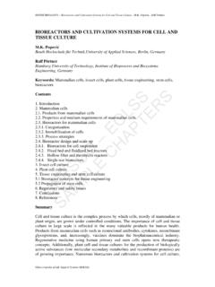
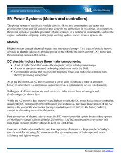
8 Single-end radial fed R. AP LS. Single-end radial fed refers to a number of customer substations or pole-mounted substations are connected to the primary substation. The supply security is the lowest C EO. as any single point failure will result in the loss of supply to the customer substation. Similarly, any single failure in the customer substation will result in loss of supply to the customer. In case of fault, the supply restoration will depend on the fault repair time. E . H. Double-end fed with an NO point PL O. To provide a higher supply security, the customer substations can be fed from two M SC. sources as shown in Figure 1. SA NE. U. Figure 1. Typical 11kV RMU open ring arrangement The customer substation is normally supplied from a single end and in the case of loss Encyclopedia of Life Support Systems ( EOLSS ).
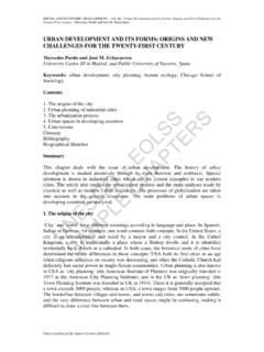
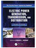
9 ELECTRICAL ENGINEERING Vol. III - Electric Power Distribution Systems - Chan of supply from the one source end, for example due to a component failure, the NO. (normally open) point can be closed to restore supply after the faulty portion of the component is isolated. The supply restoration will be quicker and is not directly depended on the fault repair time. The customer substation may consist of Rain Main Unit (RMU) and equipped with earth fault indicator as shown below. This configuration provides less secure supply since most of RMU only equipped with isolators which is unable to break fault current. This results in loss of supply in case of fault in the RMU circuit since the controlling circuit breaker at the controlling/customer substation will trip to isolate the faulty circuit. Ringed network arrangement A typical customer substation in a ring-configured network contains two feeders and one transformer feeder.
10 The former have circuit breakers and cable connecting to other substations while the latter has circuit breaker and cable connecting to 11kV/LV. S. TE S. transformer. A typical ringed network arrangement is shown in Figure 2. R. AP LS. C EO. E . H. PL O. M SC. SA NE. Figure 2. Typical 11kV close ring arrangement U. Network Configuration Distribution network refers to those 22kV or 11kV network supplying electricity to customers through cable or Overhead Line (OHL). The network configuration would directly affect the supply reliability. Of the three types of configuration, the closed ring configuration provides the highest possible supply reliability. Each customer substation has dual supply and so a single circuit fault would not cause any supply interruption. It is, in fact, aligned with N-1 approach. In the ring configuration, each feeder is protected by either high-speed feeder protection or pilot wire protection with back up overcurrent and earth fault (OC/EF) protection equipped in the primary substation.