Transcription of ELECTRICAL GROUNDING ARCHITECTURE FOR …
1 NASA-HDBK-4001 National Aeronautics andFEBRUARY 17, 1998 Space AdministrationELECTRICAL GROUNDINGARCHITECTURE FORUNMANNED SPACECRAFTNASA TECHNICAL HANDBOOKNOT MEASUREMENTSENSITIVENASA-HDBK-4001 February 17, 1998iFOREWORDThis handbook is approved for use by NASA Headquarters and all NASA Centers and isintended to provide a common framework for consistent practices across NASA handbook was developed to describe ELECTRICAL GROUNDING design ARCHITECTURE options forunmanned spacecraft . This handbook is written for spacecraft system engineers, powerengineers, and electromagnetic compatibility (EMC) engineers. spacecraft groundingarchitecture is a system-level decision which must be established at the earliest point inspacecraft design. All other GROUNDING design must be coordinated with and be consistent withthe system-level handbook assumes that there is no one single correct design for spacecraft groundingarchitecture.
2 There have been many successful satellite and spacecraft programs from NASA,using a variety of GROUNDING architectures with different levels of complexity. However, somedesign principles learned over the years apply to all types of spacecraft development. Thishandbook summarizes those principles to help guide spacecraft GROUNDING ARCHITECTURE designfor NASA and for information, corrections, or additions to this handbook should be directed to theReliability Engineering Office, Mail Code 301-456, the Jet Propulsion Laboratory, 4800 OakGrove Dr., Pasadena, CA 91109. Requests for additional copies of this handbook should besent to NASA Engineering Standards, EL01, MSFC, AL 35812 (telephone 205-544-2448).Daniel R. MulvilleChief EngineerNASA-HDBK-4001 February 17, 1998iiThis Page Left Blank IntentionallyNASA-HDBK-4001 February 17, 1998iiiTABLE OF OF OF FIGURES, TABLES, AND , standards, and of AND used in this of of GROUNDING of Structural Comments: Floating Circuits and Test ARCHITECTURE REQUIREMENTS/SELECTION of Power Distribution System: Single or Multiple Fault Isolation of the Main Power User Load Isolation From Power Distribution Interface Circuits (Command, Signal, Data, etc.)
3 Control Firing Special Items, including Cable Isolation of Support 17, spacecraft With Isolated Ground and Not Isolated Star Point , Single Reference Ground (Isolated) Ground System (Not Recommended).. Issues for spacecraft GROUNDING GROUNDING Criteria Based on spacecraft Size GROUNDING ARCHITECTURE Selection Issuesand Isolated Circuits (Hard Isolation).. Isolated Interface Circuits (Soft Isolation).. GROUNDING and Isolation Used in Various Ground Trees For Large Complex 17, 19981 ELECTRICAL GROUNDING ARCHITECTUREFOR unmanned This handbook describes spacecraft GROUNDING ARCHITECTURE options at thesystem level. Implementation of good ELECTRICAL GROUNDING ARCHITECTURE is an important part ofoverall mission success for spacecraft . The primary objective of proper GROUNDING architectureis to aid in the minimization of electromagnetic interference (EMI) and unwanted interactionbetween various spacecraft electronic components and/or subsystems.
4 Success results inelectromagnetic compatibility (EMC). This handbook emphasizes that spacecraft groundingarchitecture is a system design issue, and all hardware elements must comply with thearchitecture established by the overall system design. A further major emphasis is thatgrounding ARCHITECTURE must be established during the early conceptual design stages (beforesubsystem hardware decisions are made). The preliminary design review (PDR) time is The purpose of this handbook is to provide a ready reference forspacecraft systems designers and others who need information about system groundingarchitecture design and rationale. The primary goal of this handbook is to show designchoices that apply to a GROUNDING system for a given size and mission of spacecraft and toprovide a basis for understanding those choices and This handbook recommends engineering practices for NASA programs and projects. It may be cited in contracts and program documents as a reference forguidance.
5 Determining the suitability of this handbook and its provisions is the responsibility ofprogram/project management and the performing organization. Individual provisions of thishandbook may be tailored ( , modified or deleted) to meet specific program/project needsand constraints. The handbook is specifically intended for application to NASA unmannedspacecraft. Other spacecraft development efforts can benefit to the degree that they aresimilar in their This handbook does not cover personnel safety (such as the NationalElectrical Code) or regulatory compliance (such as Federal Communications Commissionregulations). No practice recommended in this Handbook is of structure (bonding of non- ELECTRICAL elements) is not the subject of this is a short bonding section (ref. ) that refers to another appropriate is a system level description of GROUNDING . Application to a specific design may requirereference to guidelines for specific topics such as power systems or 17, The documents cited in this handbook are listed in this section forreference.
6 Full implementation of these guidelines may require direct use of the Specifications, standards, and handbooks. The following specifications,standards, and handbooks form a part of this handbook to the extent specified OF DEFENSEMIL-B-5087-Bonding, ELECTRICAL , and Lightning Protection, for AerospaceSystemsMIL-STD-1553-Digital Time Division Command/Response Multiplex Data BusMIL-STD-1576-Electroexplosive Subsystem, Safety Requirements and TestMethods for Space SystemsMIL-STD-1773-Fiber Optics Mechanization of an Aircraft Internal Time DivisionCommand/Response Multiplex Data of precedence. Not applicable to this AND used in this current (greater than zero frequency)ACSattitude control subsystem (sometimes called Attitude Determination andControl System - ADCS)COTS commercial off-the-shelfC&DHcommand and data handling (sometimes called Command and DataManagement System - CDMS)dcdirect current (zero frequency)EEDE lectro Explosive Device (squibs.)
7 Pyrotechnic devices)EMCelectromagnetic compatibilityEMIelectromagnetic interferenceend-circuitas used in this handbook, end-circuit refers the transmitting or receivingcircuit that acts as an interface to cabling and another support equipmentH-fieldmagnetic fieldI/FinterfaceJPLJet Propulsion LaboratoryNASA-HDBK-4001 February 17, 19983k kilohmkgkilogramMmillionmmeterM megohmmAmilliampereMHzmegahertzMILmilita ryN/Anot applicablePDRpreliminary design reviewpFpicofaradPWRpower subsystempyropyrotechnicRFradio frequencyRFSradio frequency subsystemRIUremote interface unit (an external add-on element of circuitry to meetinterface requirements without modifying existing hardware designs)RTGradioisotope thermoelectric generatorRtnreturnS/CspacecraftSPGsingle -point groundSTDstandardstrstructureVMEV ersa Module Euro card (bus standard)VvoltWwatt<less than>greater than F (uF)microfarad of Concepts. This section introduces and defines concepts andnomenclature used in this handbook.
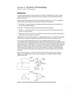
8 The ground referencing system must not only be a directcurrent (dc) voltage reference but an alternating current (ac) zero-potential system fordeliberate high-frequency signals and incidental high-frequency noise, such as noise causedby dc-dc switching power converters that are common in modern spacecraft . Simpleillustrations are used here; Section 4 provides greater 17, 19984As an example of the system level of coverage discussed in this handbook, see Figure 1 shows a sample spacecraft , with radio frequency subsystem (RFS), attitude controlsubsystem (ACS), and a power subsystem (PWR). Other subsystems are omitted from thisfigure for clarity. A spacecraft consists of the flight hardware (as contrasted with the nonflightsupport equipment). Many of the following drawings show subsystems only, with thespacecraft frame (chassis) assumed but not 1. Model spacecraft With SubsystemsAlthough the emphasis is at the spacecraft or system level, if a single assembly or experimentis relatively large, it also could be considered as a system, and the GROUNDING architectureconsiderations discussed here could be applied to it separately.
9 Figure 2 shows some drawingnomenclatures used in this common ground;triangle is sometimesleft out for ground; maynot be shown for " " identifies oneof several separatecircuit commons(see appendix A)Signal return wireexiting box(no connectionto box wall)Always bondbox to chassis(direct orbond strap) or FrameFIGURE 2. Drawing Nomenclature/KeyNASA-HDBK-4001 February 17, 19985 Isolation of grounds is an important concept. Isolation means the net dc and ac extraneous ornoise current is substantially reduced (the best isolation is no noise current whatsoever) in theisolated interface. If there is a dc signal ground connection between two assemblies and theyeach also have a separate wire ground to chassis, their signal interfaces are not isolated fromeach other. Figure 3 illustrates both isolation of grounds between two subsystems and alsolack of isolation (permitting a ground loop). Signal return current can flow both in the returnwire as well as through the chassis ground connections.
10 An example of a dc isolated interfacebetween assemblies is a transformer used to transmit ac power; there is no dc path betweenthe isolationbetween boxesKEY: dc isolated(transformer for example)signal or power interfacecircuitloopdc isolationbetween circuitcommonsdc returnwiresCircuit common referencewires attached to chassisgroundFIGURE 3. DC Isolated Ground and Not Isolated GroundGround loops can be troublesome because they can both radiate and receive magnetic fieldnoise. AC magnetic field noise can couple into and disturb other circuits. DC magnetic fieldscan disturb onboard dc magnetometers. The key to minimizing the effects of ground loops isto minimize the enclosed area around which current flows. Ideally, every power and signalinterface circuit will have 100 percent of its current (over all frequencies) return on a dedicatedreturn wire in close proximity to the outgoing power or signal lines (wires) connecting the subsystem common to the chassis actually consist of a seriesresistance, a series inductance, and various capacitances to nearby objects, all of which affectthe performance of the GROUNDING ARCHITECTURE .