Transcription of Electrical Resistivity as a Function of Temperature
1 Department of Chemical Engineering and Materials ScienceMike MeierUniversity of California, DavisSeptember 13, 2004(1)(2)(3) Electrical Resistivity AS A Function OFTEMPERATUREI ntroductionThe ability of materials to conduct electric charge gives us the means to invent an amazing array ofelectrical and electronic devices, especially considering the extraordinarily wide range ofconductivity available, with insulators on one end and superconductors on the other. (Semi-conductors, thermoelectric materials, opto-electronic materials and magneto-resistive materials arewhole other matters) Between these extremes are materials which offer a small degree of resistanceto flow of electrons, such as ordinary copper wire used in household wiring, nichrome heater wireused in toasters and ovens, and many other useful materials. This experiment focuses on theresistance of wires made of materials such as copper and nichrome, or more specifically, theresistivity of copper and nichrome as functions of The Electrical conductivity of materials is generally expressed by the equationwhere n is the number of charge carriers, q is the charge of the ion, electron or hole, and : is themobility of the charged species.
2 The value of q is either the charge of an electron or a hole, but maybe several times that if the charge is carried by multivalent ions. Resistivity The Resistivity of materials is simply the inverse of the conductivityand the Temperature dependence of Resistivity is often represented by the empirical relationshipwhere D0 is the Resistivity at a reference Temperature , usually room Temperature , and " is thetemperature coefficient. Typical values of D0 and " are listed in table 1 along with the calculatedresistivity at 100 C. In metals, where the valence electrons easily move in and out of the conduction bands, the numberof charge carriers n is large. Resistivity in metals is therefore more a Function of the mobility of theelectrons. In a perfect crystalline lattice the electrons are accelerated by an electric field and movewith very little difficulty. Even in a pure material, thermal oscillations of the atoms will scatterthese moving electrons.
3 , increasing the Resistivity somewhat. Impurity atoms and defects suchvacancies, dislocations, twin and grain boundaries, will scatter these electrons even more. Thecombined effect of thermal, impurity, and defects on the Resistivity is given by Mathesson s rulewhere(5)For pure elements the contribution of defects is on the order of percent of the total but forheavily cold worked metals it can be as high as 5 1. Resistivity values of common metals [1]MaterialD0microohm@cm"microohm@cm/K Note 1 Resistivity at100 , Hard 1. Determined at 25 CResistance Resistance is an extrinsic property of a device which is represented by the equationwhere A is the cross-sectional area and l its length. Practical devices are manufactured using anumber of techniques and geometries, including: Winding a metal wire on a cylindrical ceramic core. These resistors generally have a highpower ratings.
4 Coating a cylindrical ceramic core with a material that has the desired the film thickness and length (the film may be applied in a helical pattern) iscritical. Applying a thin film of a material with the desired Resistivity to a flat ceramic firing or curing this film can be laser trimmed to obtain a more precise resistance.(4)This method is used to put many resistors on a single SIP or DIP resistor practical applications the Temperature dependence of the resistance of a device may be an selecting a resistor for use in a circuit one can specify this the thermal tolerances along withits resistance value and power experiment has two parts, performing preliminary calculations to , then the resistivitymeasurements made in the laboratory. Perform the following calculations using spreadsheets orsimilar software tools: Calculate the Resistivity of all of the materials listed in table 1 from room Temperature to1000 C and examining the range of values and the trends.
5 Calculate the resistance of these materials when they are in the form of 2 meter lengths of24 gage wire. Calculate the output voltages from Wheatstone bridge where R1=R2=1000 ohms, R3=1 the lead resistance is experiment involves the following steps: Preheat the tube furnace to a suitably high Temperature , such as 800 C, but not high enoughto melt the sample. Set up the data acquisition system (Figure 2 shows how the equipment is connected.) Short the leads to the Wheatstone bridge to find the lead resistance. Test the system using several low-resistance ( to 2 ohms) resistors. Prepare the sample by cutting a two meter length of wire, straightening it, measuring its length, thenclean it using alcohol. Wrap the wire around a small diameter rod, then carefully slip it over aslightly larger diameter ceramic tube, making sure the coils do not touch each other. Insert thethermocouple in this tube and this assembly is placed inside another ceramic tube.
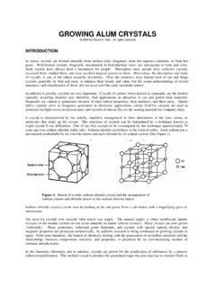
6 Figure 1 On the left are a number of different types of resistors, including c, , and 1 watt axial resistors, single anddual in-line networks, precision wire wound resistors and four tiny surface mount resistors. On the right is a magnifiedimage of a couple of the carbon film resistors in SIPs and DIPs like those shown on the left. The little hats are lasertrimmed to obtain a resistance within 2% of the desire the thermocouple and wire to the data logging system and then insert the assembly into thetube furnace. Once the sample assembly reaches the desired Temperature remove it from the furnace,place it on a heat resistant surface, and the immediately start the data acquisition software. The dataacquisition software will record and plot Temperature versus resistance. Figure 3 shows a screenshot of the data acquisition software and the last page in this manuscript is a sample printout. Oncethe sample assembly has cooled it can be safely disassembled and the wire inspected for excessiveoxidation, shorting, or other potential the data into a spreadsheet to plot it and analyze the results.
7 From the measured resistanceand wire dimensions the values of D0 and " can be The results obtained in this experiment are fairly straightforward and it seems the only questionwould be do the results compare well with the values listed in table 1, and do the results agree withthe calculations? Problems, if they are encountered, might be due to the experimental apparatus andprocedure (lead resistance errors, Temperature gradient along the wire, different Temperature at thethermocouple and the wire) or due to overlooked materials issues, such as oxidation,recrystallization, phase changes. How would these factors affect the results? Do you see any ofthese problems in the data?Figure 2 The basic equipment setup used in this CRC Handbook of Chemistry and Physics, 65th edition, CRC Press, Inc, Boca Raton, FL, pp. F-114 - F-120, (1984-85).Figure 3 Screen shot of the data acquisition 1.
8 AWG Wire GagesWire GageDiameter in mils at20 CDiameter inmillimeters at 20 2. Wheatstone BridgeThis experiment uses a standard wheatstone bridge. In the circuit used here RA and RB serve ascurrent limiting resistors for cases where R and R3 are low, such as during a short circuit whenconfigured to measure low values of R. The circuit diagram is shown in figure EquationsVS is the voltage of the power source, such as a battery and is typically volts. Higher voltagescan lead to high current passing through the 1 - 2 ohm resistor being measured. All resistor valuesare in 4 This circuit is a standard wheatstone bright that has twocurrent limiting resistors (RA and RB) and a selection or resistors R3-1 -R3-5) that allows one to select the best resistance 3. Safety ConsiderationsChemical HazardsThe methanol used to clean the wire poses fire and health hazards. Handle this solvent carefully. Use only small quantities, clean up anyspills immediately, and keep it and its fumes away from the hotfurnaces.
9 An MSDS for methanol can be provided on HazardsBurns The temperatures used in this experiment can cause seriousburns and even fires if flammable materials come in contact with thehot parts. Be extremely careful when working with the furnaces andthe hot specimens, be careful and deliberate when removing andhandling the hot specimens, and remember, parts do not have to beglowing to be very hot. Electrical There is a minor Electrical hazard in this experiment,similar to that one .. with when dealing with any small electricalappliance. Fire The combination of high temperatures, Electrical appliances,and flammable methanol presents a definite fire hazard. Keep themethanol away from the furnaces, clean up any spills immediatelyand work with on small quantities of this flammable EquipmentRecommended: safety glassesRequired: heat-resistant gloves, as neededResistivity Recording for the Keithley 199 DMM/ScannerVersion: alpha, October 24, 2002 ProjectName: Resistivity : Resistance- Temperature Recording for the Keithley 199 DMM/ScannerOwner: K Street Technology CenterData File: ParametersThermocouple Type: KResistance VS: voltsResistance RA: ohmsResistance RB: ohmsResistance R1: ohmsResistance R2: ohmsResistance R3: ohmsResistance RL: ohmsDMM/Scanner ParametersDMM Status String: n/aFunction: DC VoltsChannel 1: TemperatureRange: 300 mVChannel 2: V0 Resolution: 4 digitsChannel 3: ResistanceSampling ParametersPeriod: 1 secondChannels Scanned: 1 through 3 Start Time: 09/02/04, 22:47:41 End Time: 09/02/04, 22:48:26 Duration: 0:00.
10 45 ( s)Samples: 47 CommentsPrinted on Thursday, September, 2, 2004, 10:49:00 pm080160240320400480560640720800 Temperature , CNEW Update 2004 Resistance- Temperature Recording for the Keithley 199 DMM/ScannerSample , ohms