Transcription of ELECTRICAL RESISTIVITY METHOD - GEOVision
1 ELECTRICAL RESISTIVITY METHOD The ELECTRICAL RESISTIVITY METHOD involves the measurement of the apparent RESISTIVITY of soils and rock as a function of depth or position. The RESISTIVITY of soils is a complicated function of porosity, permeability, ionic content of the pore fluids, and clay mineralization. The most common ELECTRICAL methods used in hydrogeologic and environmental investigations are vertical ELECTRICAL soundings ( RESISTIVITY soundings) and RESISTIVITY profiling. During RESISTIVITY surveys, current is injected into the earth through a pair of current electrodes, and the potential difference is measured between a pair of potential electrodes.
2 The current and potential electrodes are generally arranged in a linear array. Common arrays include the dipole-dipole array, pole-pole array, Schlumberger array, and the Wenner array. The apparent RESISTIVITY is the bulk average RESISTIVITY of all soils and rock influencing the current. It is calculated by dividing the measured potential difference by the input current and multiplying by a geometric factor specific to the array being used and electrode spacing. In a RESISTIVITY sounding, the distance between the current electrodes and the potential electrodes is systematically increased, thereby yielding information on subsurface RESISTIVITY from successively greater depths.
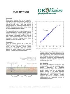
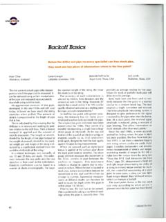
3 The variation of RESISTIVITY with depth is modeled using forward and inverse modeling computer software. GEOV ision geophysicists apply RESISTIVITY sounding techniques to: OYO McOHM 21 RESISTIVITY SYSTEM Characterize subsurface hydrogeology Determine depth to bedrock/overburden thickness Determine depth to groundwater Map stratigraphy Map clay aquitards Map salt-water intrusion Map vertical extent of certain types of soil and groundwater contamination Estimate landfill thickness In RESISTIVITY profiling, the electrode spacing is fixed, and measurements are taken at successive intervals along a profile. Data are generally presented as profiles or contour maps and interpreted qualitatively.
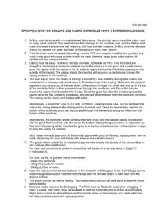
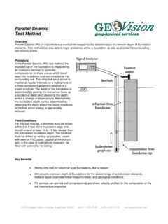
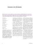
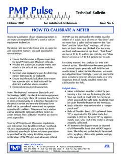
4 GEOV ision geophysicists apply RESISTIVITY profiling techniques to: Map faults RESISTIVITY ELECTRODES CONNECTED BY MULTICORECABLE Map lateral extent of conductive contaminant plumes Locate voids and karsts 3B, 4, shale(30 to 55 ohm-m)location of sectionLimestone(> 55 ohm-m)3M(20 to 30 ohm-m)2,3T(< 20 ohm-m)10203040506070809010011012000100 200 300400 500600 700800 9001000 1100 feet example of RESISTIVITY image profile using multilayer inversion at SLAPS, St. Louis, MO, July 1994 Conceptual Model Map heavy metals soil contamination Delineate disposal areas Map paleo-channels Explore for sand and gravel Map archaeological sites When information on both the lateral and vertical extent of a subsurface feature is desired, it is common to combine the sounding and profiling techniques.
5 The recent advent of auto-mated data acquisition systems has made it possible to very efficiently gather 2-D RESISTIVITY data. With these systems it is possible to lay out a large portion of the line, connect the electrodes to the data acquisition system using multi-core cable or intelligent nodes, and have the RESISTIVITY system auto-matically gather all of the measurements using preprogrammed arrays. The RESISTIVITY data is then downloaded to a computer and modeled using 2-D forward and inverse modeling software. a bold new vision in geophysical services