Transcription of ELECTRICAL SYSTEMS - BoaterEd
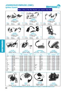
1 4E72938 ELECTRICAL SYSTEMSWIRING DIAGRAMS4E - 0 - WIRING DIAGRAMS90-816462 2-695 Table of ContentsPageWiring Colors for MerCruiser4E - 1.. Wiring Diagrams4E - 2.. Engine Wiring Diagram (Breaker Points Ignition)4E - 2.. Engine Wiring Diagram (DDIS Ignition)4E - 3.. Engine Wiring Diagram (EST Ignition)4E - 4.. instrumentation Wiring Diagram (Battery Meter Circuit)4E - 5.. Instrument Wiring Harness4E - 7.. Breaker Point Ignition - Dual Station Using A Neutral Safety Switch In Only One Remote Control4E - 7.. EST and DDIS ignition - Dual Station Using A Neutral Safety Switch In Only One Remote Control4E - 8.
2 PageBreaker Point Ignition - Dual Station Using A Neutral Safety Switch In Both Remote Controls4E - 9.. EST and DDIS Ignition - Dual Station Using A Neutral Safety Switch In Both Remote Controls4E - 10.. Battery Meter Gauge4E - 11.. Cruiselog4E - 11.. Fuel Gauge and Sender4E - 11.. Audio Warning System4E - 12.. Water Temperature Gauge4E - 12.. Oil Pressure Gauge4E - 12.. Clock4E - 12.. 4E - WIRING DIAGRAMS90-816462 2-695 WIRING DIAGRAMS - 4E - 190-816462 2-695 Wiring Colors for MerCruiserBIA COLOR CODE AND ABBREVIATIONSWHERE USEDBLACK (BLK)All GroundsBROWN (BRN)Reference Electrode-MerCathodeORANGE (ORN)Anode Electrode-MerCathodeLIGHT BLUE/WHITE (LIT BLU / WHT)Trim- Up SwitchGRAY (GRY)Tachometer SignalGREEN/WHITE (GRN / WHT)Trim - Down SwitchTAN (TAN)Water Temperature Sender to GaugeLIGHT BLUE (LIT BLU)Oil Pressure Sender to GaugePINK (PNK)
3 Fuel Gauge Sender to GaugeBROWN/WHITE (BRN / WHT)Trim Sender to Trim GaugePURPLE/WHITE (PUR / WHT)Trim- Trailer SwitchRED (RED)Unprotected Wires from BatteryRED/PURPLE (RED / PUR)Protected (Fused) Wires from BatteryRED/PURPLE (RED / PUR)Protected (+12V) to Trim PanelORANGE (ORN)Alternator OutputPURPLE/YELLOW (PUR / YEL)Ballast BypassPURPLE (PUR)Ignition Switch (+12 V)YELLOW/RED (YEL / RED)Starter Switch to Starter Solenoid to Neutral StartSwitch4E - 2 - WIRING DIAGRAMS90-816462 2-695 Wiring Engine Wiring Diagram (Breaker Points Ignition)
4 50726 CHOKESHIFTINTERRUPTSWITCHALTERNATOROPTIO NAL AUDIOWARNING WATER TEMPERATURE HEATSWITCHWATERTEMPERATURESENDEROPTIONAL OILPRESSURESWITCHTERMINALBLOCKENGINEGROU ND GROUND STUD ONENGINE FLYWHEELHOUSING GROUND SCREW ONINNER TRANSOMPLATE CIRCUITBREAKERSTARTER SLAVESOLENOIDTRIMSENDEROIL PRESSURESENDERWIRING DIAGRAMS - 4E - 390-816462 Engine Wiring Diagram (DDIS Ignition)50727 WATERTEMPERATURESENDERALTERNATORCHOKESHI FTINTERRUPTSWITCHTERMINALBLOCKENGINEGROU ND GROUND STUD ONENGINE FLYWHEELHOUSING GROUND SCREW ONINNER TRANSOMPLATE CIRCUITBREAKEROIL PRESSURESENDEROPTIONAL OILPRESSURESWITCHSTARTER SLAVESOLENOIDTRIMSENDEROPTIONAL AUDIOWARNING WATER TEMPERATURE HEATSWITCH4E - 4 - WIRING DIAGRAMS90-816462 Engine Wiring Diagram (EST Ignition)NEWSTYLEBOTTLEOLDSTYLEBOTTLENOT E 1: Audio Warning system Standard On ModelsNOTE 2.
5 Gray lead for use with service - Ignition ComponentsB - Starting , Charging and Choke ComponentsC - Audio Warning system ComponentsD - instrumentation ComponentsWIRING DIAGRAMS - 4E - 590-816462 2-695 instrumentation Wiring Diagram (Battery Meter Circuit)NOTE 1: Connect wires together with screw and hex nut. Tighten securely and coat with Liquid Neoprene to helpcontrol corrosion: when dry, slide neoprene sleeve over 2: Power for a fused accessory panel may be taken from this connection. Load must not exceed 40 ground wire must be connected to instrument terminal that has an 8-gauge BLACK (ground) harness wire connected to 3: Audio warning is standard models and optional on !
6 CAUTIONA udio warning buzzer is not external ignition proof, therefore, DO NOT mount buzzer in engine or fuel PRESSUREWATER TEMPERATUREBATTERY METERAUDIO WARINGBUZZER (OPTIONAL)TRIM INDICATORIGNITION SWITCH20 AMPFUSENOTE 1 & 2 NOTE 1 BLK = BLACKBLU = BLUEBRN = BROWNGRY = GRAYGRN = GREENORN = ORANGEPNK = PINKPUR = PURPLERED = REDTAN = TANWHT = WHITEYEL = YELLOWLIT = LIGHTDRK = DARKE arlier Style Audio Warning Buzzer4E - 6 - WIRING DIAGRAMS90-816462 2-695 NOTE 1: Connect wires together with screw and hex nut.
7 Tighten securely and coat with Liquid Neoprene to helpcontrol corrosion: when dry, slide neoprene sleeve over 2: Power for a fused accessory panel may be taken from this connection. Load must not exceed 40 ground wire must be connected to instrument terminal that has an 8-gauge BLACK (ground)harness wire connected to 3: Audio warning is standard models and optional on MeterTo Engine HarnessNOTE 3 TrimIndicatorNOTE 1 NOTE 1 NOTE 274046 Later Style Audio Warning BuzzerWIRING DIAGRAMS - 4E - 790-816462 2-695 Instrument Wiring Harness (Dual Station)
8 BREAKER POINT IGNITION - DUAL STATION USING A NEUTRAL SAFETY SWITCH IN ONLY ONEREMOTE CONTROLFUSEKEY SWITCHWATERTEMPERATUREOILPRESSUREBATTERY METERTACHOMETERPRIMARY STATIONSTART/STOPPANELWATERTEMPERATUREOI LPRESSUREBATTERY METERTACHOMETERSECONDARY STATIONNOTE 2 NOTE 3 NOTE 1 NOTE 4 NOTE 1 NOTE 4 NOTE 4 NOTE 250731 EXTENSION HARNESSTO ENGINEBLK = BLACKBLU = BLUEBRN = BROWNGRY = GRAYGRN = GREENORN = ORANGEPNK = PINKPUR = PURPLERED = REDTAN = TANWHT = WHITEYEL = YELLOWLIT = LIGHTDRK = DARKNOTE 1: BROWN/WHITE wire is taped back at instrument end.
9 If installing on boat that is equipped withMerCruiser Stern Drive, BROWN/WHITE wire is connected to the trim sender terminal block. Also canbe used for an accessory (limit 5 amps).NOTE 2: An accessory fuse panel may be connected at this location. The combined current draw of the primarystation and secondary station MUST NOT exceed 5 3: Tape back and insulate with at least four layers of ELECTRICAL 4: Connect wires together with screw and hex nut. Tighten securely and coat with Liquid Neoprene to helpcontrol corrosion.
10 When dry, slide neoprene sleeve over - 8 - WIRING DIAGRAMS90-816462 2-695 EST AND DDIS IGNITION - DUAL STATION USING A NEUTRAL SAFETY SWITCH IN ONLY ONEREMOTE CONTROL50730 KEY SWITCHWATERTEMPERATUREOILPRESSUREBATTERY METERTACHOMETERPRIMARY STATIONSTART/STOPPANELWATERTEMPERATUREOI LPRESSUREBATTERY METERTACHOMETERSECONDARY STATIONNOTE 2 NOTE 3 NOTE 4 NOTE 1 NOTE 2 EXTENSION HARNESSTO ENGINENOTE 4 FUSENOTE 4 NOTE 1 NOTE 4TO WHT/GRN CONNECTIONON TERMINAL BLOCK ATSHIFT PLATE CUT-OUTSWITCH (ON ENGINEROCKER ARM COVER)