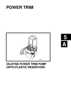
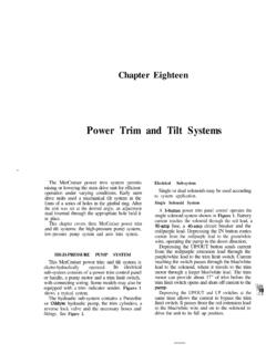
Transcription of POWER TRIM - boatfix.com
1 C526345 POWER TRIMPRESTOLITE POWER trim PUMP5C-0 PRESTOLITE POWER trim PUMP90-12934--2 1097 Table of ContentsPageIdentification5C-1.. Specifications5C-1.. Valve Pressure Specifications5C-1.. Electrical Specifications5C-1.. Lubricants/Sealers/Adhesives5C-1.. Special Tools5C-1.. Description5C-2.. Thermal Circuit Breaker Operation5C-2.. Manual Release Valve Operation5C-2.. Maintaining POWER trim Pump Oil Level5C-2.. Air Bleeding POWER trim System5C-3.. Bleeding OUT/UP trim Circuit5C-3.. Bleeding IN/DOWN trim Circuit5C-3.
2 Testing POWER trim Pump5C-4.. Connecting Test Gauge5C-4.. Internal Restriction Test5C-5.. OUT/UP Pressure Test5C-5.. IN/DOWN Pressure Test5C-5.. trim Cylinder Internal Leak Test5C-5.. trim Cylinder Shock Piston Test5C-7.. Motor and Electrical Bench Tests5C-7.. trim Pump Motor Test (In Boat)5C-7.. trim Pump Motor Test (Out of Boat)5C-8.. Solenoid Test (Pump in Boat)5C-9.. Solenoid Test (Pump Out of Boat)5C-10.. 110 Amp Fuse Test (Pump in Boat)5C-11.. 110 Amp Fuse Test (Pump Out of Boat)5C-12.. 20 Amp Fuse Test5C-12.
3 PageTrim Pump Removal5C-13.. Hydraulic Repair5C-13.. Manual Release Valve Replacement5C-13.. Disassembly5C-13.. Valve Body and Gear Assembly5C-14.. Motor Repair5C-15.. Disassembly5C-15.. Armature Tests5C-17.. Continuity Test5C-17.. Test For Shorts5C-17.. Cleaning Commutator5C-17.. Field Test5C-17.. Test For Open Circuit5C-17.. Test For Short In Field5C-18.. Thermal Switch Test5C-18.. Continuity Test5C-18.. Brush Lead Tests5C-18.. Brush Replacement5C-19.. Brush Replacement5C-19.. End Cap And Brush Assembly Replacement5C-19.
4 Reassembly5C-20.. trim Pump Installation5C-22.. Wiring Diagram5C-23.. PRESTOLITE POWER trim PUMP - 5C-190-12934--2 1097 IdentificationSome MerCruiser Sterndrives will be equipped witha Prestolite POWER trim pump. This pump was usedinterchangeably with the Oildyne pump for a periodof POWER trim PumpSpecificationsValve Pressure SpecificationsValvePressureUp Circuit2200 - 2600 PSl(15173 - 17932 kPa)Down Circuit400 - 600 PSl(2759 - 4138 kPa)Electrical SpecificationsPump Amperage Draw115 Amps at2200 - 2600 PSl(15173 - 17932 kPa)
5 Lubricants/Sealers/AdhesivesDescriptionP art trim and SteeringFluid92-90100A122-4-C Marine Lubricant92-825407A2 Liquid Neoprene92-25711-2 Special ToolsDescriptionPart Gauge Kit91-52915A6 Multi-Meter91-99750 Torque Wrench (lb. ft.)91-36210 Torque Wrench (lb. in.)91-66274 Jumper WireObtain Locally5C-2 PRESTOLITE POWER trim PUMP90-12934--2 1097 DescriptionThe Prestolite POWER trim Pump has internal valvingthat eliminates the need for an external reverse lock,as was required in the past. The pump generates ahigher volume of fluid, but at a lower pressure thanprevious Prestolite pumps.
6 This, in conjunction withlarge hydraulic hoses (gimbal housing to pump)and larger trim cylinders, should allow the driveunit to kick-up easier if an underwater object isstruck.!CAUTIONDue to differences in internal valving, the newPrestolite trim pump cannot be used to replacean earlier Prestolite pump, or vice-versa. Use ofincorrect pump will affect trim operation and maycause damage to trim pump motor is protected from overheating by aninternal circuit breaker (on commutator end plate),that interrupts the current flow through the field wind-ings in the event of an overheating condition.
7 Electri-cal current overload protection is provided to thepump by a 110 amp fuse. Pump also is fitted with a20 amp in-line fuse, which serves to protect the trimcontrol and harness from an Circuit BreakerOperationIf the IN/DOWN or Trailer switch is kept depressedafter drive unit reaches its end of travel, a thermalcircuit breaker will open to prevent pump motor fromoverheating and pump motor will stop. Releaseswitch(es) as soon as drive unit reaches end oftravel, to prevent this from happening.
8 If circuitbreaker should open, allow motor to cool down andcircuit breaker will automatically Release ValveOperation!WARNINGB efore loosening manual release valve, makesure all persons are clear of sterndrive case of a POWER trim system malfunction, thesterndrive unit can be raised and lowered manuallyby turning the manual release valvecounterclockwise approximately 3 turns and movingdrive unit to desired position by hand. After drive unithas been placed in the desired position, close valveCOMPLETELY.
9 POWER trim system will not functionproperly, unless valve is completely POWER TrimPump Oil Level!CAUTIONVent screw MUST BE backed out two (2) full turns(after bottoming out) to vent pump TO BACK SCREW OUT COULD RE-SULT IN DAMAGE TO : Check oil level with sterndrive unitin the full down : SAE 10W-30 or 10W-40 engine oilcan be used in system, if Quicksilver POWER Trimand Steering Fluid is not Place drive unit in the full IN/DOWN Remove Fill screw from pump. Oil level shouldbe up to bottom of the threads in Fill screw necessary, add Quicksilver POWER trim andSteering Fluid or SAE 10W-30 or 10W-40 motoroil (through Fill screw hole).
10 NOTE: In tropical areas, single viscosity SAE 30 mo-tor oil can be - Fill Screwb - Vent Screwc - Manual Release Valve3. Raise and lower drive unit 6 to 10 times to purgeany air from system; then, recheck oil level (withdrive unit fully IN/DOWN) and add oil POWER trim PUMP - 5C-390-12934--2 1097 Air Bleeding POWER TrimSystemThe POWER trim System will purge itself of a smallamount of air by raising and lowering the drive unitseveral times. However, if a rebuilt trim cylinder isbeing installed (which has not been filled with oil), thefollowing bleeding procedure should be used toremove the air from the OUT/UP trim Circuit1.