Transcription of ELECTRICALSAFETYTESTERS - elsinco
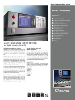
1 ELECTRICAL SAFETY TESTERSW ings for Your NOTEFour Principal Tests forEvaluating the Safetyof Electrical and Electronic ProductsHipot and Insulation Resistance TesterHigh-EndHigh-performance type suitable for R&D, Quality Assurance, and Automatic testing SystemsTOS92015kV/100mA(500VA)ACW6 (DC25V 1000V)IR19kgWD430W 132H 370 DmmRise TimeFall to 14 TOS92005kV/100mA(500VA) (DC25V 1000V)IRGPIBRS-232C19kgWD430W 132H 370 DmmRise TimeFall TimeTimerTOS9220 88H 370 DmmP. 7 StandardTOS8870A5kV/100mA(500VA)ACW1MW 1000MW (DC500V)2MW 2000MW (DC1000V)IR23kgWD430W 132H to 16 TOS510110kV/50mA(500VA)ACW10kV/5mADCW21k gWD430W 177H ,21 TOS5051A5kV/100mA(500VA)ACW5kV/10mADCWRS -232C16kgWD320W 132H to 24 W High-voltage scanner (4ch) for TOS9201/9200* TOS9221 is equipped with a contact check functionHipot TesterStandard type suitable for production and inspection linesLow-cost type most suitable for plants/factories producing in Asian marketsTOS SERIESSELECTION GUIDEThe Electrical Appliance & Material Safety Low (Japan), UL ( ), CSA (Canada), VDE (Germany) and BS ( ) are some major examples of safety standards in use throughout the world that require the performing of hipot testing .
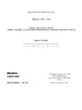
2 For this reason, it is necessary to confirm for what portion of what standard testing is to be performed when purchasing a hipot tester. Although the 500 VA capacity hipot testers available from KIKUSUI can basically be ap-plied to tests specified in all safety standards, we recommend that you consult with us prior to purchase in order to select the model that best matches your specific SERIESELECTRICAL SAFETY to to 292kgWD215W 66H 5000MW (DC25V 1000V) (6A 60A)11kgWD430W 88H to 325kgWD320W 88H 270 DmmTOS320030 A 30mA (RMS) to (3A 30A)9kgWD430W 88H ,34 GPIBRS-232 CTimerUSBRise TimeEquipped with rise time control functionFall TimeEquipped with fall time control functionGPIBE quipped with GPIB interface as standardRS-232 CEquipped with RS-232C interface as standardDimensionsDWeightWACWIRDCWE quipped with timer to 245kV/100mA(500VA)ACW15kgWD320W 132H ,265kV/100mA(500VA)
3 ACWACW22kgWD320W 132H 420 DmmRise TimeTimer Data Acquisition Software (for TOS5051A/5050A) Remote Control Box Test Probe Test Lead Warning Light Unit Buzzer Unit Calibrator for a W. Tester High-voltage Digital Voltmeter Load resistor for calibration of a hipot to 40 Insulation Resistance TesterGround Bond TesterOptions8 XXX'C' are models designed specifically for use in China. The operation panel and operation manual are in simplified range of insulation resistance testingMax. output-voltage of AC hipot testingMax. output-voltage of DC hipot testingLeakage Current TesterAGlossaryThe terms used in the description of the electrical safety tests is explained below. For a spe-cific definition of each term, refer to the relevant safety definitions of the terms indicated here are basically excerpts from the IEC 61010-1 2ndEdition.
4 Excerpts from other standards are indicated in terms concerning safetyHazardPotential source of LiveCapable of rendering an electric shock or electric burn in normal condition or sin-gle fault (of a part)Able to be touched with a standard test finger or test InsulationInsulation, the failure of which could cause a risk of electric InsulationIndependent insulation applied in addition to basic insulation in order to provide protection against electric shock in the event of a failure of basic InsulationInsulation comprising both basic insulation and supplementary InsulationInsulation which provides protection against electric shock not less than that pro-vided by double extra low voltage (SELV)Voltage across two locations that are safe to touch under normal or single fault distance in air between two conductive partsCreepage DistanceShortest distance along the surface of the insulating material between two con-ductive providing protection of equipment against certain external influence and, in any direction, protection against direct TestTest of one or more samples of equipment (or parts of equipment) made to a par-ticular design, to show that the design and construction meet one or more requirements of the TestTest to which each individual device (equipment) is subjected during or after manufacture to ascertain whether it conforms to certain electricity supply system to which the equipment concerned is designed to be connected for the purpose of powering the Circuit (Primary Circuit)
5 Circuit which is intended to be conductively connected to the mains for the pur-pose of powering the concerning the equipment classes and conditionsTerms concerning withstanding voltage and insulation resis-tance testsTerms concerning earth continuity testTerms concerning leakage current testClass 0 EquipmentEquipment where protection against electric shock is achieved only by basic 0I EquipmentEquipment in which protection against electric shock is achieved by using basic insulation and a connection to an external protective earthing system. Equipment that cannot be connected to the fixed mains socket with an earthing terminal using a mains power cord that contains a protective earthing conductor. (JIS C 1004-96)Class I EquipmentEquipment in which protection against electric shock is achieved by using basic insulation and also providing a means of connection to the protective earthing conductor wiring those parts that are otherwise capable of assuming hazardous voltages if the basic insulation II EquipmentEquipment in which protection against electric shock does not relay on basic insulation only, but in which additional safety precautions, such as double insula-tion or reinforced insulation are provided.
6 There being no reliance on protective III EquipmentEquipment in which protection against electric shock relies upon supply from SELV circuits and which hazardous voltages are not ConditionCondition in which all means for protection against hazards are Fault ConditionCondition in which one means for protection against hazard is defective or one fault is present which could cause a Test, Dielectric Strength Test, hipot TestThese terms are all equivalents of the withstanding voltage test. Dielectric strength test is commonly used in the safety standards. Various names are used on the products of equipment Conductor Te r m i n a lTerminal which is bonded to conductive parts of an equipment for safety pur-poses and is intended to be connected to an external protective earthing BondingElectrical connection of accessible conductive parts or protective screening to provide electrical continuity to the means of connection of an external protective Current CircuitA circuit which is so designed and protected that, under both normal operating conditions and single fault conditions, the current which can be drawn is not haz-ardous.
7 (IEC 60950-1)Touch CurrentElectrical current through a human body when it touches one or more accessible parts. Current that is measured using a body impedance network (body model) that matches the body Conductor CurrentCurrent flowing through the protective earthing conductor under normal operating Impedance Network, Measurement NetworkCircuit network (body model) representing the human body impedance that is used in the measurement of the TC. There are differences in the body response types and safety standards. However, it is usually defined using resistors and ResponsesBody responses when a hazardous current flows. There are four types of responses: perception, reaction, let-go, and electric burn. (IEC 60990)BFour Principal Tests for Evaluating the Safety of Electrical and Electronic ProductsElectrical products consists of many parts.
8 Mostly, they are composed of electric parts thatconduct electricity (conductors) and those that block electricity (insulators). If the insulatorbetween parts that are accessible by humans and parts that are hazardous is defective, elec-tric shock may occur if a human being touches the electric equipment. If the defective insulat-ing part heats up, it may cause a fire. To prevent such accidents, evaluating the safety ofelectric equipment is extremely important. The typical tests are withstanding voltage test,insulation resistance test, leakage current test, and earth continuity test. Withstanding voltage and insulation resistance testsThese tests check whether the insulation performance of insulation section (solid insula-tion, clearance, etc.) between hazardous section and accessible section are sufficient.
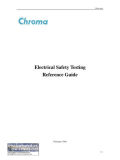
9 Leakage current testThis test measures the amount of current that flows assuming the case in which a humanactually touches the electric equipment. Earth continuity testThis test checks whether the protective bonding is achieved by low resistance for equip-ment designed to use protective earthing for securing four tests are mandatory type tests that must be executed under the safety standardssuch as IEC and UL as well as the Electrical Appliance and Material Safety Law. The with-standing voltage and earth continuity tests that are performed between the primary circuit(parts connected to the commercial power line that may become an immediate threat) andaccessible locations are routine tests that must be performed on all products on a B-1 Safety evaluation testNLPEZ1Z2 EnclosureElectronic EquipmentSecondaryPrimaryMainsAccessible conductive partElectric shock occurs if the impedance of Z1 and Z2 is Principal Tests for Evaluating the Safety of Electrical and Electronic ProductsWithstanding Voltage TestThe withstanding voltage test evaluates whether the electric insulation section of an electricequipment or parts have sufficient dielectric strength for the working voltage.
10 It is also calleddielectric withstand test or hipot this test, a voltage stress that is much higher than the voltage that is normally applied tothe insulation section for a specific time to see whether a dielectric breakdown occurs. If acurrent flowing through the insulation section exceeds the limit during the test period, it isassumed that a dielectric breakdown occurred. If a dielectric breakdown does not occur, theinsulator is assumed to have sufficient dielectric principle of the withstanding voltage testFig. B-2 Withstanding voltage testAC test and DC testFor the test between the primary circuit and an accessible section as shown in Fig. B-2, anAC voltage is normally applied. If a filter for eliminating the electromagnetic interference ispresent in the location corresponding to Z1 or Z2 and its capacitive component is large, thedistinction between the current flowing through the filter and the current used to assume adielectric breakdown will be difficult.