Transcription of ELECTRO-PNEUMATIC - Ultra Bird
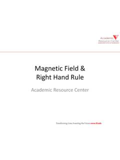
1 ELECTRO-PNEUMATIC Push button switches A push button is a switch used to close or open an electric control circuit. They are primarily used for starting and stopping of operation of machinery. This causes set of contacts to open or close. Push buttons are of two types i) Momentary push button ii) Maintained contact or detent push button Push button switches Momentary push buttons return to their unactuated position when they are released. Maintained (or mechanically latched) push buttons has a latching mechanism to hold it in the selected position. The contact of the push buttons, distinguished according to their functions, i) Normally open (NO) type ii) Normally closed (NC) type iii) Change over (CO) type.
2 In the NO type, the contacts are open in the normal position, inhibiting the energy flow through them. But in the actuated position, the contacts are closed, permitting the energy flow through them. Normally open (NO) type In the NC type, the contacts are closed in the normal position, permitting the energy flow through them. And, the contacts are open in the actuated position, inhibiting the energy flow through them. Normally closed (NC) type A changeover contact is a combination of NO and NC contacts. Changeover contact Direct and Indirect Control: Direct Control: The piston rod of a single-acting cylinder is to be extended when pushbutton S1 is pressed and retracted when the pushbutton is released.
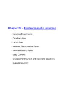
3 Indirect Control: If the pushbutton is pressed in an indirect control system, current flows through the relay coil. Contact K1 of the relay closes, and the directional control valve switches. The piston rod advances. Direct Control of Single Acting Cylinder: The electrical circuit diagram for direct control of a single-acting cylinder is shown in Figure. Direct Control of Single Acting Cylinder: Forward stroke: The circuit is closed when push button PB closes. magnetic field is produced in the coil Y. Armature in the coil opens the passage for the compressed air. The compressed air flows from 1 to 2 of the 3/2 DCV to cylinder, which travels to the final forward position.
4 Direct Control of Single Acting Cylinder: Return stroke: When the push button PB is released, circuit is interrupted. magnetic field at coil Y collapses, the 3/2 way valve switches back to its original position. The compressed air in the cylinder then exhausts through port 3 of the DCV and the cylinder travel to the final rear position. Direct Control of Double Acting Cylinder (extended): The electrical circuit diagram for direct control of a double-acting cylinder is shown in Figure. Direct Control of Double Acting Cylinder (extended): Forward stroke: The double acting cylinder is controlled by 5/2 way valve.
5 When the pushbutton PB is pressed, coil Y is energised and the directional control valve is activated by compressed air via pilot control. The piston travels to the final forward position. Direct Control of Double Acting Cylinder (retracted): Return stroke: On release of PB, circuit is interrupted. magnetic field at coil Y collapses, the return spring of 5/2 becomes active and the 5/2 way valve switches back to its original position. The compressed air in the cylinder then exhausts through port 5 of the 5/2 DCV and the cylinder travel to the final rear position. A relay is an electro magnetically actuated switch.
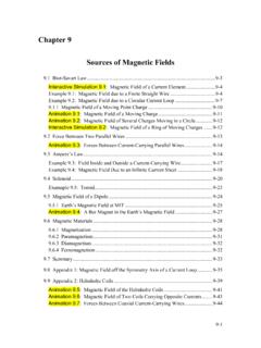
6 It is a simple electrical device used for signal processing. Relays are designed to withstand heavy power surges and harsh environment conditions. RELAY When a voltage is applied to the solenoid coil, an electromagnet field results. This causes the armature to be attracted to the coil core. The armature actuates the relay contacts, either closing or opening them, depending on the design. A return spring returns the armature to its initial position when the current to the coil is interrupted. Indirect Control of Single Acting Cylinder The electrical circuit diagram for indirect control of a single-acting cylinder is shown in Figure.
7 Indirect Control of Single Acting Cylinder Return stroke: On release of PB, circuit is interrupted. This de-energises a relay K1. The magnetic field at coil Y is collapses due to the opening of contact K1 the 3/2 way valve switches back to its original position. The compressed air in the cylinder then exhausts through port 3 of the DCV and the cylinder travel to the final rear position. Indirect Control of Single Acting Cylinder Forward stroke: The circuit is closed when push button PB closes. Closing of PB energises a relay K1. The coil Y is energised via normally open contact K1 (indirect energising).
8 A magnetic field is produced in armature of the coil Y opens the passage for the compressed air. The compressed air flows from 1 to 2 of the 3/2 DCV to cylinder, which travels to the final forward position. In-direct Control of Double Acting Cylinder (extended): The electrical circuit diagram for in-direct control of a double-acting cylinder is shown in Figure. In-direct Control of Double Acting Cylinder: (retracted) The electrical circuit diagram for in-direct control of a double-acting cylinder is shown in Figure. Indirect Control of double acting cylinder (using 5/2 way, double solenoid ) Indirect Control of double acting cylinder (using 5/2 way, double solenoid ) Forward stroke: When PB1 is pressed, coil Y1 is energised and 5/2 way DCV changes over.
9 Piston travels out and remains in the final forward position until a signal is applied to coil Y2. The 5/2 DCV will remain in the last position because it is double solenoid valve and has no return spring. Indirect Control of DAC (using double solenoid ) Return stroke: When the push button PB1 is released and PB2 is pressed. Opening of Push button PB1 de-energises a relay K1. magnetic field at coil Y1 is collapses due to opening of contact K1. Closing of PB2 energises Y2 and the piston returns to its original position as a result of changeover of the 5/2 way valve. Control of double acting cylinder OR logic (Parallel circuit) The piston of a DAC is to travel out when either one of two pushbutton switch is pressed.
10 It is to return when both are released. When PB1 or PB2 are pressed coil Y1 is energised. The DCV switches over and the piston travels to the final forward position. When both the PB switches are released, the signal is removed from Y1 and the cylinder travels back to its original position. Control of double acting cylinder OR logic (Parallel circuit) Control of double acting cylinder AND logic (Series circuit) The piston of a DAC is to travel out when both push button switch is pressed. If only one PB is pressed, there is no movement. When PB1 or PB2 are pressed coil Y1 is energised.