Transcription of Chapter 11 Inductance and Magnetic Energy
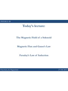
1 Chapter 11 Inductance and Magnetic Energy Mutual Example Mutual Inductance of Two Concentric Coplanar Example Self- Inductance of a Example Self- Inductance of a Example Mutual Inductance of a Coil Wrapped Around a Energy Stored in Magnetic Example Energy Stored in a Animation : Creating and Destroying Magnetic Animation : Magnets and Conducting RL Self- Inductance and the Modified Kirchhoff's Loop Rising Decaying LC The RLC Series Appendix 1: General Solutions for the RLC Series Quality Appendix 2: Stresses Transmitted by Magnetic Animation : A Charged Particle in a Time-Varying Magnetic Problem-Solving Calculating Circuits containing Solved Energy stored in a Magnetic Energy Mutual RL RL LC Conceptual Additional Coupled RL RL Inductance of a solenoid With and Without Iron RLC Spinning Spinning 11-2 Inductance and Magnetic Energy Mutual Inductance Suppose two coils are placed near each other, as shown in Figure Figure Changing current in coil 1 produces changing Magnetic flux in coil 2.
2 The first coil has N1 turns and carries a current I1 which gives rise to a Magnetic field 1BG. Since the two coils are close to each other, some of the Magnetic field lines through coil 1 will also pass through coil 2. Let 21 denote the Magnetic flux through one turn of coil 2 due to I1. Now, by varying I1 with time, there will be an induced emf associated with the changing Magnetic flux in the second coil: 2121212coil 2ddNdtdt d = = BAGG ( ) The time rate of change of Magnetic flux 21 in coil 2 is proportional to the time rate of change of the current in coil 1: 21122dNMdtdt1dI = ( ) where the proportionality constant21 Mis called the mutual Inductance . It can also be written as 221211 NMI = ( ) The SI unit for Inductance is the henry (H): 11-3 ( ) 21 henry1 H1 Tm/A== We shall see that the mutual inductance21M depends only on the geometrical properties of the two coils such as the number of turns and the radii of the two coils.
3 In a similar manner, suppose instead there is a current I2 in the second coil and it is varying with time (Figure ). Then the induced emf in coil 1 becomes 1212121coil 1ddNdtdt d = = BAGG ( ) and a current is induced in coil 1. Figure Changing current in coil 2 produces changing Magnetic flux in coil 1. This changing flux in coil 1 is proportional to the changing current in coil 2, 122112dNMdtdtdI = ( ) where the proportionality constant 12 Mis another mutual Inductance and can be written as 112122 NMI = ( ) However, using the reciprocity theorem which combines Ampere s law and the Biot-Savart law, one may show that the constants are equal: 1221 MMM= ( ) 11-4 Example Mutual Inductance of Two Concentric Coplanar Loops Consider two single-turn co-planar, concentric coils of radii R1 and R2, with 12RR , as shown in Figure What is the mutual Inductance between the two loops?
4 Figure Two concentric current loop Solution: The mutual Inductance can be computed as follows. Using Eq. ( ) of Chapter 9, we see that the Magnetic field at the center of the ring due to I1 in the outer coil is given by 01112 IBR = ( ) Since12RR , we approximate the Magnetic field through the entire inner coil by1B. Hence, the flux through the second (inner) coil is 2201012211221122 IIRBARRR === ( ) Thus, the mutual Inductance is given by 20221112 RMIR == ( ) The result shows that M depends only on the geometrical factors, 1R and 2R, and is independent of the current 1I in the coil. Self- Inductance Consider again a coil consisting of N turns and carrying current I in the counterclockwise direction, as shown in Figure If the current is steady, then the Magnetic flux through the loop will remain constant.
5 However, suppose the current I changes with time, 11-5then according to Faraday s law, an induced emf will arise to oppose the change. The induced current will flow clockwise if , and counterclockwise if /dIdt>0/0dIdt<. The property of the loop in which its own Magnetic field opposes any change in current is called self- Inductance , and the emf generated is called the self-induced emf or back emf, which we denote as L . All current-carrying loops exhibit this property. In particular, an inductor is a circuit element (symbol ) which has a large self- Inductance . Figure Magnetic flux through the current loop Mathematically, the self-induced emf can be written as BLddNNdtdt d = = BAGG ( ) and is related to the self- Inductance L by LdILdt = ( ) The two expressions can be combined to yield BNLI = ( ) Physically, the Inductance L is a measure of an inductor s resistance to the change of current; the larger the value of L, the lower the rate of change of current.
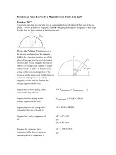
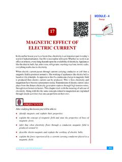
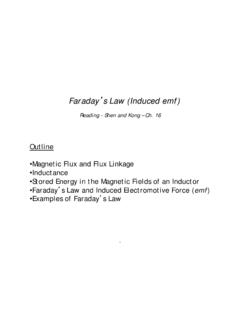
6 Example Self- Inductance of a solenoid Compute the self- Inductance of a solenoid with turns, length l, and radius NR with a current I flowing through each turn, as shown in Figure 11-6 Figure solenoid Solution: Ignoring edge effects and applying Ampere s law, the Magnetic field inside a solenoid is given by Eq. ( ): 00 NInIl ==BkkG ( ) where is the number of turns per unit length. The Magnetic flux through each turn is /nNl= 200()B2 BAnIRnIR == = ( ) Thus, the self- Inductance is 220 BNLnI Rl == ( ) We see that L depends only on the geometrical factors (n, R and l) and is independent of the current I. Example Self- Inductance of a Toroid Calculate the self- Inductance of a toroid which consists of N turns and has a rectangular cross section, with inner radius a, outer radius b and height h, as shown in Figure (a).
7 (a) (b) Figure A toroid with N turns 11-7 Solution: According to Ampere s law discussed in Section , the Magnetic field is given by ( ) 0(2)dBdsBdsBrN ==== BsGGvvvI or 02 NIBr = ( ) The Magnetic flux through one turn of the toroid may be obtained by integrating over the rectangular cross section, with dAh dr= as the differential area element (Figure ): 00ln22bBaNINI hbdhdrra = == BAGG ( ) The total flux is . Therefore, the self- Inductance is BN 20ln2 BNhNbLIa == ( ) Again, the self- Inductance L depends only on the geometrical factors. Let s consider the situation where ab. In this limit, the logarithmic term in the equation above may be expanded as a lnln1bbabaaaa =+ ( ) and the self- Inductance becomes 220022 NhNANAbaLaal ==20 )a ( ) where is the cross-sectional area, and (Ahba= 2l =.
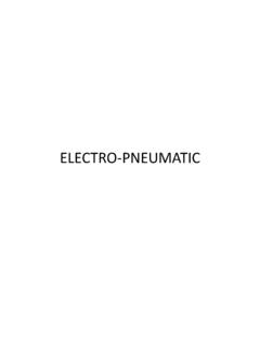
8 We see that the self- Inductance of the toroid in this limit has the same form as that of a solenoid . Example Mutual Inductance of a Coil Wrapped Around a solenoid A long solenoid with length l and a cross-sectional area A consists of N1 turns of wire. An insulated coil of N2 turns is wrapped around it, as shown in Figure 11-8 (a) Calculate the mutual Inductance M, assuming that all the flux from the solenoid passes through the outer coil. (b) Relate the mutual Inductance M to the self-inductances and of the solenoid and he coil. 1L2L Figure A coil wrapped around a solenoid Solutions: (a) The Magnetic flux through each turn of the outer coil due to the solenoid is 01121 NIBAlA == ( ) where 011/BNIl =is the uniform Magnetic field inside the solenoid . Thus, the mutual Inductance is 0122211 NNANMIl == ( ) (b) From Example , we see that the self- Inductance of the solenoid with N1 turns is given by 20111111 NANLIl == ( ) where is the Magnetic flux through one turn of the solenoid due to the Magnetic field produced by 11 1I.
9 Similarly, we have for the outer coil. In terms of and , the mutual Inductance can be written as 2202/LNA =l1L2L 12 MLL= ( ) More generally the mutual Inductance is given by 12, 01 MkLLk= ( ) 11-9 where is the coupling coefficient. In our example, we have k1k= which means that all of the Magnetic flux produced by the solenoid passes through the outer coil, and vice versa, in this idealization. Energy Stored in Magnetic Fields Since an inductor in a circuit serves to oppose any change in the current through it, work must be done by an external source such as a battery in order to establish a current in the inductor. From the work- Energy theorem, we conclude that Energy can be stored in an inductor. The role played by an inductor in the Magnetic case is analogous to that of a capacitor in the electric case.
10 The power, or rate at which an external emf ext works to overcome the self-induced emf L and pass current I in the inductor is extextLdWPdtI == ( ) If only the external emf and the inductor are present, then extL = which implies extLLdWdIPIdtdt == =+IL00 ( ) If the current is increasing with , then which means that the external source is doing positive work to transfer Energy to the inductor. Thus, the internal Energy of the inductor is increased. On the other hand, if the current is decreasing with , we then have . In this case, the external source takes Energy away from the inductor, causing its internal Energy to go down. The total work done by the external source to increase the current form zero to /dIdt>0P>BU/dIdt<0P<I is then 2extext01''2 IWdWLIdIL=== I ( ) This is equal to the Magnetic Energy stored in the inductor: 212 BUL=I ( ) The above expression is analogous to the electric Energy stored in a capacitor: 212 EQUC= ( ) 11-10 We comment that from the Energy perspective there is an important distinction between an inductor and a resistor.