Transcription of Finite Element Analysis
1 Finite Element AnalysisDavid RoylanceDepartment of Materials Science and EngineeringMassachusetts institute of TechnologyCambridge, MA 02139 February 28, 2001 IntroductionFinite Element Analysis (FEA) has become commonplace in recent years, and is now the basisof a multibillion dollar per year industry. Numerical solutions to even very complicated stressproblems can now be obtained routinely using FEA, and the method is so important that evenintroductory treatments of Mechanics of Materials { such as these modules { should outline itsprincipal spite of thegreat power of FEA, the disadvantages of computer solutions must bekept inmind when using this and similar methods.}}
2 They do not necessarily reveal how the stresses areinfluencedbyimportantproblemvariables suchasmaterialspropertiesandgeometricalf eatures,and errors in input data can produce wildly incorrect results that may be overlooked by theanalyst. Perhaps the most important function of theoretical modeling is that of sharpening thedesigner's intuition; users of nite Element codes should plan their strategy toward this end,supplementing the computer simulation with as much closed-form and experimental Analysis elementcodes areless complicated thanmanyof thewordprocessingandspreadsheetpackages found on modern microcomputers.
3 Nevertheless, they are complex enough that mostusers do not nd it e ective to program their own code. A number of prewritten commercialcodes are available, representing a broad price range and compatible with machines from mi-crocomputers to supercomputers1. However, userswith specialized needs should notnecessarilyshy away from code development, and may nd the code sources available in such texts as thatby Zienkiewicz2to beausefulstartingpoint. Most niteelement software is written inFortran,but some newer codes such asfeltare in C or other more modern programming practice, a nite Element Analysis usually consists of three principal :The user constructs amodelof the part to be analyzed in which the geom-etry is divided into a number of discrete subregions, or \ elements ," connected at discretepoints called \nodes.
4 " Certain of these nodes will have xed displacements, and otherswill have prescribed loads. These models can be extremely time consuming to prepare,and commercial codes vie with one another to have the most user-friendly graphical \pre-processor" to assist in this rather tedious chore. Some of these preprocessors can overlayamesh on a preexisting CAD le, sothat nite Element Analysis can bedoneconvenientlyas part of the computerized drafting-and-design Brebbia, ed., Finite Element Systems, A Handbook,Springer-Verlag, Berlin, Zienkiewicz and Taylor,The Finite Element Method,McGraw-Hill Co., London, :The dataset prepared by the preprocessor is used as input to the nite elementcodeitself, which constructs and solves a system of linear or nonlinear algebraic equationsKijuj=fiwhereuandfarethedisplac ementsandexternallyappliedforcesatthenod alpoints.
5 Theformation of theKmatrix is dependent on the type of problem being attacked, and thismodule will outline the approach for truss and linear elastic stress analyses. Commercialcodes may have very large Element libraries, with elements appropriate to a wide rangeof problem types. One of FEA's principal advantages is that many problem types can beaddressed with the same code, merely by specifying the appropriate Element types fromthe :In the earlier days of nite Element Analysis , the user would pore throughreams of numbers generated by the code, listing displacements and stresses at discretepositions within the model.
6 It is easy to miss important trends and hot spots this way,and modern codes use graphical displays to assist in visualizing the results. A typicalpostprocessor display overlays colored contours representing stress levels on the model,showing a full- eld picture similar to that of photoelastic or moire experimental operation of a speci c code is usually detailed in the documentation accompanying thesoftware, andvendorsofthemoreexpensivecodeswilloft eno erworkshopsortrainingsessionsas well to help users learn the intricacies of code operation. One problem users may have evenafter this training is that the code tends to be a \black box" whose inner workings are notunderstood.
7 Inthismodulewewilloutlinetheprinciplesun derlyingmostcurrent niteelementstress Analysis codes, limiting the discussion to linear elastic Analysis for now. Understandingthis theory helps dissipate the black-box syndrome,and also serves to summarize the analyticalfoundations of solid Analysis of trussesPin-jointed trusses, discussed more fully in Module 5, provide a good way to introduce FEAconcepts. The static Analysis of trusses can be carried out exactly, and the equations of evencomplicated trusses can be assembled in a matrix form amenable to numerical solution. Thisapproach, sometimes called \matrix Analysis ," provided the foundation of early FEA Analysis of trusses operates by considering the sti ness of each truss Element oneat a time, and then using these sti nesses to determine the forces that are set up in the trusselements by the displacements of the joints, usually called \nodes" in nite Element noting that the sum of the forces contributed by each Element to a node must equal theforce that is externally applied to that node.
8 We can assemble a sequence of linear algebraicequations in which the nodal displacements are the unknowns and the applied nodal forces areknown quantities. These equations are conveniently written in matrix form, which gives themethod its name: K11K12 K1nK21K22 Knn = 2 Hereuiandfjindicate the deflection at theithnode and the force at thejthnode (thesewould actually be vector quantities, with subcomponents along each coordinate axis). TheKijcoe cient array is called theglobal stiffness matrix,withtheijcomponent being physically theinfluence of thejthdisplacement on theithforce. The matrix equations can be abbreviated asKijuj=fiorKu=f(1)using either subscripts or boldface to indicate vector and matrix the forceexternally appliedor the displacement is known atthe outset foreach node,and it is impossible to specify simultaneously both an arbitrary displacementanda force on agiven node.
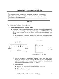
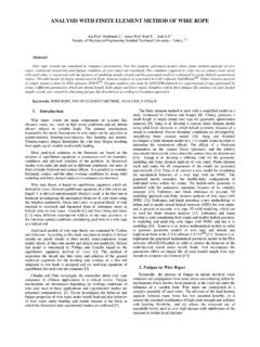
9 These prescribed nodal forces and displacements are the boundary conditions ofthe problem. It is the task of Analysis to determine the forces that accompany the imposeddisplacements, and the displacements at the nodes where known external forces are matrix for a single truss elementAs a rst step in developing a set of matrix equations that describe truss systems, we need arelationshipbetweentheforcesanddisplace mentsateachendofasingletrusselement. Considersuch an Element in thex yplane as shown in Fig. 1, attached to nodes numberediandjandinclined at an angle from the 1: Individual truss the elongation vector to be resolved in directions along and transverse to theelement, the elongation in the truss Element can be written in terms of the di erences in thedisplacements of its end points: =(ujcos +vjsin ) (uicos +visin )whereuandvare the horizontal and vertical components of the deflections, respectively.
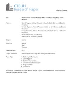
10 (Thedisplacements at nodeidrawn in Fig. 1 are negative.) This relation can be written in matrixform as: =[ c scs] uiviujvj Herec=cos ands=sin .TheaxialforcePthataccompanies theelongation isgivenbyHooke's lawforlinearelasticbodiesasP=(AE/L) . Thehorizontal andvertical nodalforces are shownin Fig. 2; these canbe written in terms of the total axial force as:3 Figure 2: Components of nodal force. fxifyifxjfyj = c scs P= c scs AEL = c scs AEL[ c scs] uiviujvj Carrying out the matrix multiplication: fxifyifxjfyj =AEL c2cs c2 cscs s2 cs s2 c2 cs c2cs cs s2cs s2 uiviujvj (2)The quantity in brackets, multiplied byAE/L, is known as the \ Element sti ness matrix"kij.