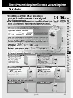
Transcription of Electro-Pneumatics M1 Student - Quia
1 electro - pneumatic Module 1: Introduction to electro - pneumatics PREPARED BY. Academic Services August 2012. Applied Technology High Schools, 2012. ATM-414 Electro-Pneumatics Module 1: Introduction to electro - pneumatics Module Objectives After the completion of this module, the Student will be able to: 1- Explain all safety precaution when working with Electro-Pneumatics . 2- Explain the concept of signal flowing in Electro-Pneumatics . 3- Identify the advantages and disadvantages of the elector- pneumatics. Module Contents Sr Topic Page No. 1 Introduction to Electro-Pneumatics 3. 2 Signal flow in Electro-Pneumatics 4. 3 Advantages of electro - pneumatic systems 5. 4 Components of electro - pneumatic system 6. 5 Safety and operation 12. 6 Practical task 1 13.
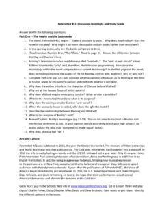
2 7 Practical task 2 17. 8 Practical task 3 18. 9 References 24. 2 Module 1: Introduction to Electro-Pneumatics ATM-414 pneumatic systems 1 Introduction to electro - pneumatics electro - pneumatic is widely used in many areas of industrial automation. Production, assembly, and packaging systems worldwide. These systems are driven by electro - pneumatic control systems. (a) and (b) show different applications of electro - pneumatic machines. (a). In Electro-Pneumatics , the pneumatic components are controlled by using electrical and electronic circuits. Electronic and electromagnetic sensors, electrical switches and industrial computers are used to replace the manual (b). control of a pneumatic system. (a): Milk filling machine (b): Yogurt filling machine Module 1: Introduction to Electro-Pneumatics 3.
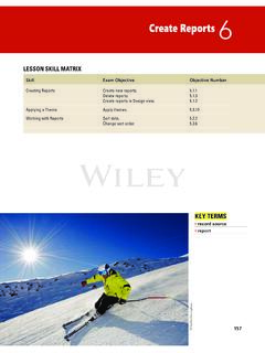
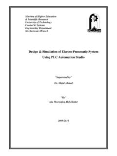
3 ATM-414 Electro-Pneumatics `. 2 Signal flow in electro - pneumatic control system The signal flow diagram of Fig. illustrates the signal flow within an electro - pneumatic system. 1. Signal input: This signal is usually generated from sensor or switch. 2. Signal processing: the signal is processed in the processing station such as OR gate, AND gate or time delay valve. 3. Signal output: the signal forms as a link between the signal control section and the power section 4. Command execution: it takes place at high power level either for: High speed-fast ejection of product. Apply high force as in power presses. Fig. : Signal flow and components of an electro - pneumatic control system 4 Module 1: Introduction to Electro-Pneumatics ATM-414 pneumatic systems 3 Advantages of electro - pneumatic systems: Below are some advantages of electro - pneumatic systems 1.
4 Greater reliability. Less moving parts subjected to wear compared to mechanical control systems. 2. Reduced installation complexity. Less components and hoses, leads to less effort in planning and commissioning especially with large and complex systems. 3. The control system can be easily modified and adapted. It is easier to change wiring and modify programs rather than changing mechanical components and hose networks. Example: the AND gate is replaced with logic and through using electrical switches. 4. Easy handling. Less complexity 5. Secure mounting. Fewer hoses 6. Environmentally-friendly coupling system. Less lubrication require 4 Components of electro - pneumatic system The electro pneumatic system is normally consists of the following items: 1.
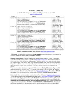
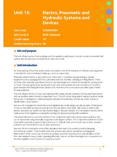
5 DC power supply. 2. Switches. 3. Relays. 4. Solenoid valves. 5. Sensor. Module 1: Introduction to Electro-Pneumatics 5. ATM-414 Electro-Pneumatics DC Power Supply The power supply is used to reduce and convert the 230 V AC to a 24 V DC. (inside ATHS laboratories) as shown in Figure power supply The power supply components which are shown in Fig. have the following functions: The transformer reduces the main voltage (230 to 24 volt). The rectifier converts the AC voltage to DC voltage. The stabilizer is used to smooth and maintain constant voltage at the output electric diagram of the power supply The following criteria play commonly an important role is selecting the power supply: The magnitude of voltage and current it can supply. How stable its output voltage or current is under varying load conditions.
6 Whether it provides continuous or pulsed energy. 6 Module 1: Introduction to Electro-Pneumatics ATM-414 pneumatic systems Switches Switches are installed in an electric circuit to connect or interrupt the electric current. These switches are divided into: 1- Control switches: keep the selected position such as detent switches. Push button switches: maintain the selected position as long as the switch is activated. In this module, three types of switches will be discussed: a. Push button switches. b. Detent switches. c. Limit switches. (a) Push button switches These switches are activated manually and used connect or disconnect the electric current in he control circuit. There are three typed of the push button switches: 1- Normally open contact (make).
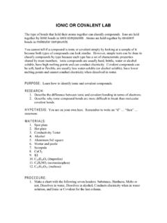
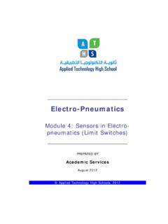
7 In the case of a normally open switch , the circuit is open if the switch is in its initial position (a) (b). Pressing the pushbutton results in closing the circuit and then the current will flow to load. When the plunger is released the spring will returns the switch to it initial position. Module 1: Introduction to Electro-Pneumatics 7. ATM-414 Electro-Pneumatics 2 Normally close contact (break). In the case of the normally closed switch Fig. , the circuit is closed when the switch is in its initial position. The circuit is (c) (d). interrupted by pressing the pushbutton. shows the ISO symbol of the push button N/C. 2 4. 3 Changeover contact (two- way). 1. The change over contact Fig. combines the function of the (e) (f). normally open and normally closed.
8 Changeover contacts are used to close one circuit and open another circuit in one switching operation. In the (ATHS) labs, these types of (g). switches are combined in one switch : block as illustrated in figure (a): push button switch (N/O). (b): ISO symbol of the normally open push button switch (c): push button switch (N/C). (d): ISO symbol of the normally closed push button switch (e): changeover switch (two way). (f): ISO symbol of the changeover switch (g): Switch block 8 Module 1: Introduction to Electro-Pneumatics ATM-414 pneumatic systems b Detent switches These switches keep the selected position; the switch position remains unchanged until a new switch position is selected. It is called detent switch or a latching switch. and (a). show the ISO symbol of the normally open detent switch and normally closed detent switch respectively.
9 Detent switches also designed to be as (b). normally open, normally closed or changeover switches. In the (ATHS) labs, the detent switches are included in the same switch block with pushbutton switches, as shown in (c). Fig. Fig. : (a): ISO symbol of normally open detent switch (b): ISO symbol of normally closed detent switch c Limit switches (c): Switch block The limit switch ( ) is actuated when a machine part or a work-piece is in a certain position. Normally, actuation is affected by a cam or cylinder piston. Limit switches are normally changeover (a) (b). Module 1: Introduction to Electro-Pneumatics 9. ATM-414 Electro-Pneumatics contacts and can be connected according to the required control circuit. The limit switch can be used in circuit according to one of the following: Normally open switch Normally closed switch Changeover switch Fig.
10 (a): internal construction of the limit switch (b): ISO symbol of the limit switch (c): picture of the limit switch 10 Module 1: Introduction to Electro-Pneumatics ATM-414 pneumatic systems Relays A relay is defined as an electromagnetically actuated switch. When the voltage is applied to a solenoid coil terminals (A1, A2) in , it will become an electromagnet which in turn attracts the contacts of the relay either closing (a). or opening them. The spring returns the contacts to the initial position immediately after disconnecting the voltage at the coil terminals. (b). An ISO symbol of the relay and a lab relay block is also illustrated in the same figure. Some advantages of a relay that: It can be used to switch one or more contacts. To switch a high current circuit with a low current circuit.