Transcription of Electrochemical Migration Resistance Test
1 1 ScopeThis test method provides a means to assess thepropensity for surface Electrochemical Migration . This testmethod can be used to assess soldering materials Applicable IPCIPC-B-25 Multipurpose Test BoardIPC-B-25 AMultipurpose Test BoardIPC-6012 AQualification and Performance Specification forRigid Printed BoardsIPC-9201 Surface Insulation Resistance American Society for Testing and Materials (ASTM)ASTM D-257-93 Standard Test Methods for DC Resistanceor Conductance of Insulating Materials3 Test SpecimensIPC-B-25 (B or E pattern) or IPC-B-25A(D pattern) test boards shall be used, with conductor linewidths and spacings of mm [ in]. The methodof manufacture should provide optimized conductor edgedefinition (refer to the Class 2 and 3 conductor width require-ments in IPC-6012).
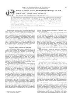
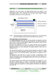
2 The finished test boards should beuntreated, bare copper, unless another surface finish is part ofthe evaluation. Figure 1 shows the IPC-B-25A test board; theD pattern is identical to the IPC-B-25 B or E pattern. For pro-cess evaluation, the test pattern board should be made usingthe same substrate material as will be used in practice toduplicate actual working Test ChamberA temperature/humidity chambercapable of producing an environment of 40 C 2 C [104 F], 93% 2% RH, 65 C 2 C [149 F], RH, or 85 C 2 C [185 F], RHand allowing test boards to be electrically biased and mea-sured without being opened under these temperature andhumidity conditions is Measuring EquipmentHigh Resistance measuringequipment, equivalent to that described in ASTM D-257-93,with a range up to 1012ohm and capable of yielding an accu-racy of 5% at 1010ohm with an applied potential of 100 VDC(10% tolerance).
3 Standard resistors should be used for Power SupplyEquipment capable of providing 10 VDC at 100 A, with a 10% tolerance, shall be Current-Limiting ResistorsUse one 106ohm resistorin each current path. This equates to three current-limitingresistors for each 5-point comb pattern. Note that some testequipment has the current limiting resistors built into the test-ing Connecting WireUse PTFE-insulated, solid-conductor, copper wire, or equivalent. (See IPC-9201 SurfaceInsulation Resistance Handbook.)IPC-26141-1 Figure 1 IPC-B-25A Test Board2215 Sanders RoadNorthbrook, IL 60062-6135 IPC-TM-650 TEST METHODS Migration Resistance TestDate09/00 RevisionOriginating Task GroupElectrochemical Migration Task GroupMaterial in this Test Methods Manual was voluntarily established by Technical Committees of IPC.
4 This material is advisory onlyand its use or adaptation is entirely voluntary. IPC disclaims all liability of any kind as to the use, application, or adaptation of thismaterial. Users are also wholly responsible for protecting themselves against all claims or liabilities for patent referenced is for the convenience of the user and does not imply endorsement by CONNECTINGELECTRONICS Other Dedicated FixturesHardwiring is the defaultconnection method. Other dedicated fixtures may be used,provided that the fixture does not change the Resistance formore than decade compared to a comparable hardwiredsystem, when measured at the test Test Specimen performing a material qualification ( , flux), allspecimens are to be cleaned and dried using a processcapable of yielding aminimuminsulation Resistance value of4x1010ohm when tested at 35 C, 85% minimum RH after24 hours.
5 If this test is being performed as a process qualifi-cation, additional pre-test processing is not minimum of three test specimens cleaned per be used for liquid flux:Apply the liquid flux to the entire surface of the test specimenby brushing liberal quantities of the flux onto the specimen, byfloating the specimen comb side down on the liquid flux, or bydipping the specimen into the flux. The specimen shall bedrained vertically for one minute with the fingers of the combpattern vertical. Alternatively, flux may be applied by produc-tion application processes - spray, foam, or wave. The edgeconnector fingers should be protected from is recommended that production wave soldering equipmentbe used for soldering the test specimens, with a preheat pro-file representative of production. A solder fountain may beused (not a solder pot), with a residence time similar to theresidence time in a solder wave.
6 Solder composition is usually60% tin 5%, remainder is lead; for such alloys, the soldertemperature shall be 250 C 6 C [482 F]. For alloysother than those with compositions near the tin-lead eutectic,the solder temperature will be compatible with the usual sol-dering temperature for the alloy any solder bridging occurs, that specimen shall be dis-carded. A minimum of three specimens from the samplegroup shall be solder paste:A squeegee or screen printer shall be used with a stencilimaged with the test pattern. It should be noted that the Tel-cordia GR-78 pattern requires a minimum stencil thickness mm [ mil]. Due to the fact that the minimum stencilthickness is often dependent on the pitch or trace width andspacing, a smaller stencil thickness may be used for fine fea-tures and shall be agreed upon between the tester and cus-tomer for the purpose of this test the printed specimens using convection, infrared, orvapor phase reflow equipment using a reflow profile represen-tative of production.
7 Equivalent methods may be used if suchequipment is not any solder bridging occurs, that specimen shall be dis-carded. The edge connector fingers should be protected minimum of three specimens from the sample group shallbe flux-cored wires:Using a hand soldering iron and the cored wire under test,carefully apply solder to the fingers of all comb patterns. Theedge connector fingers should be protected from any solder bridging occurs, that specimen shall be minimum of three specimens from the sample group shallbe tested. Each circuit path will be tested for the presence ofsolder shorts using a Resistance meter ( digital multimeter). solder cleaning shall be performed only whensuch cleaning is part of the production process used in thefinal evaluating incoming board quality and/or finalfinishes, test specimens shall be used as received or as speci-fied by the end test leads to the land areas of all patterns eitherby mechanical pressure ( , edge connectors, spring-loadedpins) or by hand soldering using Rosin (R) cored wire, using ashield to protect the test patterns from flux contamination dur-ing soldering; the flux shall not spread into the pattern not remove the Test the terminated test specimens in a suitable rackthat maintains the specimens at least cm apart and suchthat the air flow is parallel to the direction of the test speci-mens in the chamber.
8 For hardwiring, wires should Migration Resistance TestDate09/00 RevisionPage2of3dressed from the bottom to prevent flux residues from thewire attachment from flowing onto the test patterns. Withmechanical fixtures, fixtures should be to the side. Insert thelimiting resistors in terminating leads 1, 3, and 5 of each the rack approximately in the center of the testchamber. Route the wires to the outside of the chamber;dress the wiring away from the test patterns. Ensure thatdrops of condensation cannot fall on the the chamber and allow all samples to stabilizefor 96 hours at the specific temperature and humidity. Afterthe 96-hour stabilization period, the initial insulation resistancemeasurements shall be made using voltage in the range of 45 VDC to 100 VDC. Due to polarity, measurements should bemade between terminals 1 and 2, 3 and 2, 3 and 4, and 5 and4, at the specific temperature and humidity with the currentlimiting resistors placed in series with the test circuit.
9 Termi-nals 2 and 4 shall be at one potential, and terminals 1, 3, and5 at the opposite the samples to the power supply with thecurrent limiting resistors placed in series with the test circuit,and apply 10 VDC for the duration of the test. The test polar-ity shall be the same as the measurement polarity used insection 500 hours of applied bias (596 hours total), dis-connect the power supply and repeat the measurements with the specimens under test Data HandlingThe average (geometric mean) insula-tion Resistance (IRavg) is calculated from:IRavg=10[1N 1 Nlog IRi]where,N = number of test points (10 minimum),IRi= individual insulation Resistance measurementsWhere an assignable cause of low insulation Resistance , whichis properly attributable to the materials of construction or tothe process used to produce the test board, can be found,then such a value can be excluded from calculating the assignable causes include.
10 Contamination on the insulating surface of the board, suchas debris, solder splints, or water droplets from the condi-tioning chamber Incompletely etched patterns that decrease the insulatingspace between conductors by an amount greater than thatallowed in the appropriate design requirements drawing Scratched, cracked, or obviously damaged insulationbetween conductorsA minimum of 10 test measurements is required for the test tobe Visual ExaminationAfter completion of the test, thetest specimens shall be removed from the test chamber andexamined, with back-lighting, at 10x magnification for evi-dence of Electrochemical Migration (filament growth), discol-oration, and :Localized Electrochemical Migration on one comb maybe caused by a testing Reference IPC-TR-476 AElectrochemical Migration : ElectricallyInduced Failures in Printed Wiring IPC-9201 Surface Insulation Resistance Telcordia Specification of Test ConditionsUsers of this testmethod will need to specify one (1) of the three (3)temperature/humidity conditions called out in section that IPC-TR-476A recommends using 65 C, 85% Migration Resistance TestDate09/00 RevisionPage3of3