Search results with tag "Schottky"
MBRS140T3 - Surface Mount Schottky Power Rectifier
www.onsemi.comSchottky Power Rectifiers employ the use of the Schottky Barrier principle in a large area metal to silicon power diode. State of the art geometry features epitaxial construction with oxide passivation and metal overlay contact. Ideally suited for low voltage, high frequency rectification, or as free wheeling and polarity protection diodes in ...
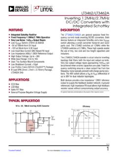
LT3462 (Rev. A) - Analog Devices
www.analog.comThe LT3462 has a built‑in Schottky diode. When supply voltage is applied to the VIN pin, the voltage difference between VIN and VD generates inrush current flowing from input through the inductor and the Schottky diode to charge the flying capacitor to V IN. The maximum non‑ repetitive surge current the Schottky diode in the LT3462
SMD-codes databook 2019 edition - Turuta
turuta.mdSBD Schottky Barrier Diode SBR Schottky Barrier Rectifier Diode SPI SPI interface SS Soft start St-dwn Step-down St-up Step-up Supress. Suppressor Sw. Switching TMBSR Trench MOS Barrier Schottky Rectifier T-MOS Trench-FET MOSFET Trd Time Reset Delay Tun Tuner U-Speed Ultra-speed UHF RF applications (>250 MHz) ULN Ultra Low-Noise UV Latched ...

MBR120VLSF, NRVB120VLSF Schottky Power Rectifier, …
www.onsemi.comSchottky Power Rectifier, Surface Mount 1.0 A, 20 V, SOD-123 Package This device uses the Schottky Barrier principle with a large area metal−to−silicon power diode. Ideally suited for low voltage, high frequency rectification or as free wheeling and polarity protection diodes in surface mount applications where compact size and weight

MBRS360T3 - Surface Mount Schottky Power Rectifier
www.onsemi.comSchottky Power Rectifier MBRS360T3G, MBRS360BT3G, NRVBS360T3G, NRVBS360BT3G, NRVBS360BNT3 This device employs the Schottky Barrier principle in a large area metal−to−silicon power diode. State−of−the−art geometry features epitaxial construction with oxide passivation and metal overlay contact.

LOW DROP POWER SCHOTTKY RECTIFIER - …
www.st.comLOW DROP POWER SCHOTTKY RECTIFIER ® Axial Power Schottky rectifier suited for Switch Mode Power Supplies and high frequency DC to DC converters. Packaged in DO-201AD these devices are intended for use in low voltage, high frequency inverters, free wheeling, polarity protection and small battery chargers. DESCRIPTION n VERY SMALL CONDUCTION LOSSES
MBRS340T3 - Surface Mount Schottky Power Rectifier
www.onsemi.comSchottky Power Rectifier MBRS320T3G, SBRS8320T3G, MBRS330T3G, NRVBS330T3G, MBRS340T3G, SBRS8340T3G These devices employ the Schottky Barrier principle in a large area metal-to-silicon power diode. State-of-the-art geometry features epitaxial construction with oxide passivation and metal overlay contact.

BAT54HT1 - Schottky Barrier Diodes
www.onsemi.comBAT54H Schottky Barrier Diodes These Schottky barrier diodes are designed for high speed switching applications, circuit protection, and voltage clamping. Extremely low forward voltage reduces conduction loss. Miniature surface mount package is excellent for hand held and portable applications where space is limited. Features

SEMICONDUCTOR DEVICE PHYSICS AND DESIGN
seklad69associates.com5.3.1 Schottky Barrier Height .....219 5.3.2 Capacitance Voltage Characteristics .....223 5.3.3 Current Flow across a Schottky Barrier: Thermionic Emission .....223 5.3.4 Comparison of Schottky and p-ndiodes . .....227 5.4 METAL SEMICONDUCTOR JUNCTIONS ...

MBR0520LT1 - Surface Mount Schottky Power Rectifier
www.onsemi.comThe Schottky Power Rectifier employs the Schottky Barrier principle with a barrier metal that produces optimal forward voltage drop-reverse current tradeoff. Ideally suited for low voltage, high frequency rectification, or as free wheeling and polarity protection diodes in surface mount applications where compact size and weight are critical to ...

BLOCKING DIODE INSTALLATION INSTRUCTIONS - Marlec
www.marlec.co.ukIt is usual to fit the blocking diode into the positive output inside the terminal box of the solar module at the positive end of each series string. In order to minimise voltage drop and power loss it is recommended that Schottky diodes are used. Modules up to 60W 5A Schottky Diode Marlec Part No 913-005
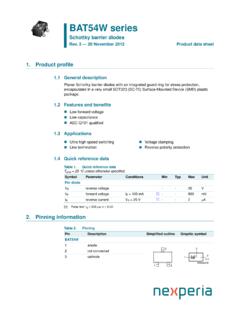
BAT54W series Schottky barrier diodes
assets.nexperia.comSchottky barrier diodes Rev. 3 — 20 November 2012 Product data sheet Ultra high-speed switching Voltage clamping Line termination Reverse polarity protection Tamb =25 C unless otherwise specified. Symbol Parameter Conditions Min Typ Max Unit Per diode VR reverse voltage - - 30 V VF forward voltage IF =100mA [1]-- 800mV

SD103AWS - SD103CWS - Diodes Incorporated
www.diodes.comDiodes Incorporated Subject: SURFACE MOUNT SCHOTTKY BARRIER DIODE Keywords: This Schottky barrier device has been designed to meet the stringent requirements of Automotive Applications. It is ideally suited to use as a:•Polarity Protection Diode •Re-Circulating Diode •Switching Diode Created Date: 9/26/2018 4:08:16 PM

BAT54SLT1 - Dual Series Schottky Barrier Diodes
www.onsemi.comThese Schottky barrier diodes are designed for high speed switching applications, circuit protection, and voltage clamping. Extremely low forward voltage reduces conduction loss. Miniature surface mount package is excellent for hand held and portable applications where space is limited.

B520C - B560C
www.diodes.com5.0A SURFACE MOUNT SCHOTTKY BARRIER RECTIFIER Keywords: This Schottky Barrier Rectifier is designed to meet the general requirements of commercial applications. It is ideally suited for use as a: · Polarity Protection Diode · Re-Circulating Diode · Switching Diode Created Date: 7/27/2015 10:08:46 AM

MBRS340 - Schottky Rectifier
www.farnell.comMBRS340 Schottky Rectifier Features • Compact Surface Mount with J-bend Leads (SMC) • 3.0 W Power Dissipation Package • 3.0 A, Forward Voltage less than 500 mV Ordering Information Absolute Maximum Ratings Stresses exceeding the absolute maximum ratings may damage the device. The device may not function or be opera-

扬州扬杰电子科技股份有限公司
static.cninfo.com.cnApr 16, 2021 · 肖特基势垒二极管(Schottky Barrier Diode),是以其发明人肖特基博 士命名的一种金属-半导体(接触)二极管 JBS 指 结势垒肖特基(Junction Barrier Schottky)二极管,是肖特基二极管的 一种优化,JBS 二极管结合了PiN 高耐压特性和SBD 低开启电压、 快恢复特性 IDM 指

Metal/Semiconductor Ohmic Contacts - Stanford University
web.stanford.educrude. An ohmic contact is generally modeled as a heavily doped Schottky (diode) contact. The Schottky model predicts that upon bringing in contact Si with electron affinity X, and a metal of work function φm, a barrier of height φb = (φm − χ) which is independent of semiconductor doping will be formed. Since measured φm values for a ...
Chapter 1 Power Electronic Devices (Part I)
pdfs.semanticscholar.orgSchottky diode (Schottky barrier diode-SBD) standard recovery Reverse recovery time and charge specified. t rr is usually less than 1μs, for many less than 100 ns —— ultra-fast recovery diode. – A majority carrier device – Essentially no recovered charge, and lower forward voltage. – Restricted to low voltage (less than 200V)

Power MOSFET Selection Guide - NXP
www.nxp.comSchottky or Schottky-like diode but without problematic high leakage current. Efficiency is excellent, even at higher frequencies, making NextPowerS3 the perfect choice for high power density DC:DC applications. #1 for Hot-swap MOSFETs In applications such as hot-swap and soft-start, power MOSFETs are deliberately turned
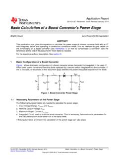
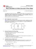
Basic Calculation of a Boost Converter's Power Stage (Rev. C)
www.ti.com4 Rectifier Diode Selection To reduce losses, Schottky diodes should be used. The forward current rating needed is equal to the maximum output current: (7) IF = average forward current of the rectifier diode IOUT(max) = maximum output current necessary in the application Schottky diodes have a much higher peak current rating than average rating.

ProblemsandSolutionsto PhysicsofSemiconductorDevices
www.physik.tu-dresden.de5. Find current densities jat room temperature for a Schottky diode Pt-n-GaAs at n = 8800 cm2 V−1 s−1, m n/m 0 = 0.063, work function of Pt is 5.65 eV, χ GaAs = 4.07 eV, Nc = 8.63 × 10¹³ × T3/2 cm−3. Apply thermionic-emission theory. 6. The capacitance of a Au-n-GaAs Schottky diode is given by the relation 1/C2 =
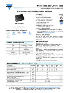
Surface-Mount Schottky Barrier Rectifier
www.vishay.comSurface-Mount Schottky Barrier Rectifier LINKS TO ADDITIONAL RESOURCES FEATURES • Low profile package • Ideal for automated placement ... SS36-M3/9AT 0.235 9AT 3500 13" diameter plastic tape and reel SS36HM3_A/H (1) 0.235 H 850 7" diameter plastic tape and reel SS36HM3_A/I (1) 0.235 I 3500 13" diameter plastic tape and reel 0 0.5 1.0 1.5 2 ...

Practical considerations when comparing SiC ... - UnitedSiC
unitedsic.comAn extra parallel SiC Schottky diode can be added to bypass the body diode, but at significant cost and with limited benefit. • With MOSFETs, the gate turn-on threshold is low, about 2.2V for SiC ... trench JFET with the JFET gate sharing a common connection to the MOSFET source. When a positive voltage is applied to the Si-MOSFET gate, it ...
Basic Calculation of a Buck Converter's Power Stage (Rev. B)
www.ti.comIF = average forward current of the rectifier diode IOUT(max) = maximum output current necessary in the application Schottky diodes have a much higher peak current rating than average rating. Therefore the higher peak current in the system is not a problem. The other parameter that has to be checked is the power dissipation of the diode. It has ...

GaN Power HEMT Tutorial: GaN Basics
iganpower.comSchottky Contact and Current Control 1,Kevin J. Chen, Understanding the Dynamic Behavior in GaN-on-Si Power Devices and IC’s, Integrated Power Conversion and Power Management, 2018 2,Greco, G., Iucolano, F., & Roccaforte, F. Review of technology for normally-off HEMTs with p-GaN gate. Materials Science in Semiconductor Processing GIT p ...

MBR20100CT - Switch-mode Power Rectifiers
www.onsemi.comThis series uses the Schottky Barrier principle with a platinum barrier metal. These state−of−the−art devices have the following features: Features • 20 A Total (10 A Per Diode Leg) • Guard−Ring for Stress Protection • Low Forward Voltage • 175°C Operating Junction Temperature • Epoxy Meets UL 94 V−0 @ 0.125 in
SiC Power Devices and Modues Application Note - Rohm
fscdn.rohm.comSchottky barrier and can usually be reduced by designing a lower barrier height. However, there is a trade-off relation between the rising voltage and the leakage current in a reverse bias condition, which increases as the barrier height decreases. In the

AN136 - PCB Layout Considerations for Non-Isolated ...
www.analog.compower stage circuit and the small signal control circuit. The power stage circuit includes the components that conduct high current. In general, these components ... and its optional paralleled Schottky diode. Figure 3a shows the parasitic PCB inductors in these high di/dt cur- ... diode, D, and high frequency output capacitor, C HF, must

SiC power modules for your electric ... - STMicroelectronics
www.st.comSchottky diode HV MOSFET/ IGBT 2x Phase shift full bridge Control unit Signal conditioning Load + MOS/IGBT Gate driver HV diode Smart controller Line input EMI stuff Phase Inductor s L1 L2 L3 ... High Power IGBT Trench Field-stop PTC Heater, OBC, HB aircon DM Higher Efficiency K Higher Voltage Range M More Power Density OBC and DC-DC converter

BL9309 5.5V 2.0A 1.3MHz Synchronous Buck Converter
atta.szlcsc.comof 1.3MHz allows the use of small external components, such as ceramic input and output caps, as well as small ... eliminates the typical Schottky free-wheeling diode. Using the on resistance of the internal high-side ... voltage-feedback signal against the sum of the amplified current-sense signal and the slope compensation

Chapter 2 - Synchronous Rectification
vtechworks.lib.vt.eduSchottky diodes in parallel with SR 2 and/or SR 3 or by minimizing the conduction times of D 2 and D 3. While the conduction time of D 3 can be minimized either by driving Q 3 by an external gate-drive signal or by minimizing the dead time by employing a …

Lecture 2. Power semiconductor devices (Power switches)
www.philadelphia.edu.jopower levels at several hundred volts and several hundred amps. normally used in high frequency circuits. 3. Schottky : very low forward voltage drop (typical 0.3V ) limited blocking voltage (50-100V) . used in low voltage, high current application such as …

1N5820 and 1N5822 are Preferred Devices Axial Lead Rectifiers
www.onsemi.comThis series employs the Schottky Barrier principle in a large area metal-to-silicon power diode. State-of-the-art geometry features chrome barrier metal, epitaxial construction with oxide passivation and metal overlap contact. Ideally suited for use as rectifiers in low-voltage, high-frequency inverters, free wheeling diodes, and

扬州扬杰电子科技股份有限公司 - 21yangjie.com
www.21yangjie.com肖特基势垒二极管(Schottky Barrier Diode),是以其发明人肖特基博 ... SGT MOS 指 分离栅沟槽功率场效应管(Split Gate Trench MOSFET) TVS 指 瞬态抑制二极管 德国美微科,德国 MCC 指 Micro Commercial Components GmbH 杰利半导体、杰利半导体公司 指 扬州杰利半导体有限公司

LTC4353 - Dual Low Voltage Ideal Diode Controller
www.analog.comIdeal Diode Controller The LTC®4353 controls external N-channel MOSFETs to implement an ideal diode function. It replaces two high power Schottky diodes and their associated heat sinks, saving power and board area. The ideal diode function permits low loss power supply ORing and supply holdup applications.

PMEG6010CEH; PMEG6010CEJ 1 A very low V F MEGA …
assets.nexperia.com[1] For Schottky barrier diodes thermal runaway has to be considered, as in some applications the reverse power losses PR are a significant part of the total power losses. [2] Device mounted on an FR4 PCB, single-sided copper, tin-plated and standard footprint.

Semiconductor Diodes - Learn About Electronics
www.learnabout-electronics.org1. Three power rectifiers, (a Bridge rectifier for use with mains (line) voltages, and two mains voltage rectifier diodes). 2. A point contact diode (with glass encapsulation) and a Schottky diode. 3. A small signal silicon diode. 4. Zener Diodes with glass or black resin encapsulation. 5. A selection of light emitting diodes. Counter-clockwise ...

Product Summary Features - Diodes Incorporated
www.diodes.com3.0A SURFACE MOUNT SCHOTTKY BARRIER RECTIFIER Product Summary B320A-B340A: V RRM (V) I O (A) V F(MAX) @ 3A I (V) R(MAX) @ V RRM (mA) 20, 30, 40 3.0 0.50 0.5 B350-B360A: V RRM (V) I O (A) V F(typ) @ +125°C (V) I R(MAX) @ V RRM (mA) 50, 60 3.0 0.70 0.5 Description and Applications Mechanical Data

CCM PFC Boost Converter Design - Mouser Electronics
www.mouser.comboost rectifier commutation recovery loss due to Q rr. For this reason, ultra-fast recovery diodes or silicon carbide schottky diodes with no charge Q rr are needed for CCM mode. In conclusion, we can say that for low power applications, the CrCM boost has an …

Edition 3.0 2016-04 INTERNATIONAL STANDARD NORME ...
webstore.iec.cha) Schottky barrier diodes and its properties are added; b) Clauses 3, 4 , 5 and 7 were amended with some deletions of information no longer in use or already included in other parts of the IEC 60747 series, and some necessary with

PMEG3020EH; PMEG3020EJ 30 V, 2 A ultra low V F MEGA ...
assets.nexperia.com[2] For Schottky barrier diodes thermal run-away has to be considered, as in some applications the reverse power losses PR are a significant part of the total power losses. Nomograms for determining the reverse power losses PR and IF(AV) rating will be available on request.

TYPICAL APPLICATION
atta.szlcsc.comNo Schottky Diode Required 4.5V to 16V Input Voltage Range 0.6V Reference GENERAL DESCRIPTIONSlope Compensated Current Mode Control for Excellent Line and Load Transient Response Integrated internal compensation Stable with Low ESR Ceramic Output Capacitors Over Current Protection with Hiccup-Mode
History of Semiconductors - Cornell University
djena.engineering.cornell.edudently developed models of the potential barrier and cur-rent flow through a metal-semiconductor junction. A year later Schottky improved his model including the presence of space charge. In 1938 Boris Davydov presented a the-ory of a copper-oxide rectifier including the presence of ap-njunctionintheoxide,excesscarriersandrecom-bination.

Schottky Barrier Plastic Rectifier - Vishay Intertechnology
www.vishay.comSchottky Barrier Plastic Rectifier FEATURES • Guardring for overvoltage protection • Very small conduction losses • Extremely fast switching • Low forward voltage drop • High frequency operation • Solder dip 275 °C max. 10 s, per JESD 22-B106
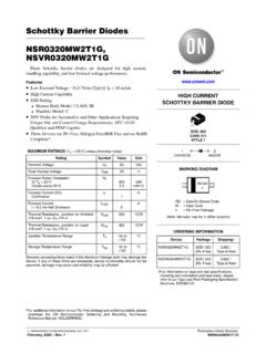
Schottky Barrier Diodes NSR0320MW2T1G, NSVR0320MW2T1G
www.onsemi.comSchottky Barrier Diodes NSR0320MW2T1G, NSVR0320MW2T1G ... Forward Power Dissipation @ TA = 25°C Derate above 25°C PF 200 2.0 mW mW/°C Forward Current (DC) Continuous IF 1 A Forward Current t = 8.3 ms Half Sinewave IFSM 5 A Thermal Resistance, Junction−to−Ambient 175 mm2, 1 oz. Cu, FR−4
Similar queries
Schottky Power, Schottky, Power, Analog Devices, Schottky Diode, Trench, Rectifier, Schottky barrier, Power Schottky rectifier, Switch Mode Power, Schottky Power Rectifier, Schottky barrier diodes, BAT54H Schottky Barrier Diodes, DIODE INSTALLATION INSTRUCTIONS, Diode, SD103AWS - SD103CWS, Diodes, Schottky Barrier Rectifier, MBRS340 - Schottky Rectifier, MBRS340 Schottky Rectifier, Plastic, Practical considerations when comparing SiC, Barrier, SiC Power Devices and, Small signal, Small, Signal, Synchronous, Semiconductor Diodes, Product Summary, SURFACE MOUNT SCHOTTKY BARRIER, CCM PFC Boost Converter Design, Mouser Electronics, Mode, Semiconductor, Schottky Barrier Plastic Rectifier, Vishay Intertechnology