Transcription of ELECTROLYTIC CAPACITORS - Yageo
1 ELECTROLYTIC RoHS Compliant ISO-9001:2000 CERTIFIEDMINIATURE aluminum ELECTROLYTIC CAPACITORS27 S5 [ For Super Miniature ] 1,000hrs. at 105 C29 SS [ For Super Miniature ] 1,000hrs. at 105 C31 SK [ For General ] 2,000hrs. at 85 C36 SE-K [ For General ] 1,000hrs. at 105 C41 SH [ For General ] 2,000hrs. at 105 C45 SG [ Electronic Ballast ] 5,000hrs. at 105 C48 SP [ Miniature and Long Life ] 10,000hrs. at 105 C50 SB [ For Low Leakage Current ] 1,000hrs. at 105 C54 SN [ For Non-Polar ] 1,000hrs. at 105 C58 SR [ For Horizontal Deflection ] 1,000hrs. at 105 C60 SC [ Low Impedance and Low ESR Suitable for Motherboard Output Termination ] 3,000hrs. at 105 C64 SJ [ Low Impedance and High Ripple Series ] 1,000~5,000hrs. at 105 C69 SQ [ For Adapter and Power Supply Applications Series ] 2,000hrs.
2 At 105 C72 SY [ For Low Impedance and Low ESR Suitable for Motherboard Output Termination ] 3,000~6,000hrs. at 105 C78 SZ [ Ultra Low ESR ] 2,000hrs. at 105 C80 ST [ Low Impedance and Long Life ] 4,000~10,000hrs. at 105 C83 SD [ For High Ripple Current ] 5,000hrs. at 105 C85 SL [ Long Life and Low Impedance ] 3,000~7,000hrs. at 105 C92 SU [ For Higher Temperature Range ] 2,000hrs. at 125 C94 SW [ Higher Temperature Range and Long Life ] 2,000~5,000hrs. at 125 CLARGE CAN aluminum ELECTROLYTIC CAPACITORS97 LH [ For Miniature ] 2,000hrs. at 85 C106 LG [ For General ] 2,000hrs. at 105 C114 LV [ For Long Life ] 3,000hrs. at 105 C121 LC [ High Temperature and Long Life ] 5,000hrs. at 105 CSURFACE MOUNT aluminum ELECTROLYTIC CAPACITORS124 CA [ For General ] 2,000hrs. at 85 C128 CB [ For General ] 1,000hrs.
3 At 105 C132 CE [ For Long Life ] 2,000hrs. at 105 C136 CZ [ For Low Impedance ] 1,000hrs. at 105 C140 CD [ For Ultra Low Impedance ] 1,000hrs. at 105 C143 CH [ Ultra Low Impedance and High Temperature ] 2,000hrs. at 125 C146 CX [ Ultra Low Impedance and Long Life ] 3,000~5,000hrs. at 105 CCONDUCTIVE POLYMER SOLID CAPACITORS149 CP [ Ultra Low ESR & High Ripple Current ] 2,000hrs. at 105 C151 CG [ Low ESR & High Ripple Current ] 2,000hrs. at 105 CSCREW TYPE aluminum ELECTROLYTIC CAPACITORS154 NP [ For General ] 2,000hrs. at 85 C159 NM [ For Wide Temperature ] 2,000hrs. at 105 C164 NF [ Long Life for Inverter ] 5,000hrs. at 85 C166 NH [ High Temperature, Long Life for Inverter ] 5,000hrs. at 105 C171 NG [ For Low Voltage, Large Capacity ] 2,000hrs. at 85 CINDEX4 Please note the following recommendations when using CAPACITORS : 1.
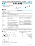
4 When using ELECTROLYTIC CAPACITORS on DC applications, polarization is required as well as the confirmation of the polarity of the course. Otherwise, the circuit life may be shortened or the capacitor may be damaged by the insertion on reverse polarity. Use non-polar CAPACITORS on those circuits with occasionally reverse polarity or unknown polarity. Also note that do not use ELECTROLYTIC CAPACITORS for AC Do not apply a voltage exceeding the capacitor rated voltage, that will cause the capacitor be damaged by increased leakage Use the ELECTROLYTIC capacitor at current value under the permissible ripple range. 4. Use the ELECTROLYTIC CAPACITORS according to the specified operation temperature range. Using at room temperature will ensure a longer The ELECTROLYTIC capacitor is not suitable for circuits which are charged and discharged repeatedly.
5 If used in circuits which are charged and discharged repeatedly, the capacitance value may drop or the capacitor may be damaged. Please consult our engineering department for assistance in these When CAPACITORS have been left unused for a long time, use them only after due voltage treatments. Long storage time may raise capacitor's leakage current level. In such cases, be sure to provide the necessary voltage treatment before Be careful of the temperature and time conditions when soldering. Adverse effects may happen on the electrical characteristics and insulation sleeve of ELECTROLYTIC CAPACITORS may occur in case the soldering temperature is too high or dipping time too long. For small-size ELECTROLYTIC CAPACITORS , proper dipping shall be executed at temperature lower than 260 C for less than 10 Clean circuit boards after soldering.
6 Halogenated hydrocarbon cleaning solvents are not recommended to clean CAPACITORS with exposed end seals. If halogenated solvent is required, order and use CAPACITORS in Epoxy-coated end Do not apply excessive force to the lead wires or terminals. It may break the components or disconnect the internal elements on the board. (For strength of terminals, please refer to JIS C5102 and C5141.)10. Keep the clearance between the vent of the capacitor and the case of the appliance. Do not block the operation of the vent, unless otherwise described on the catalogues or product specifications. The narrower clearance may adversely affect the vent operation and result in the capacitor The description in this catalogue is subject to change without prior notice for product improvement.
7 Therefore, please confirm the specification before ordering products. The general characteristics, reliability data, etc., described in this catalogue should not be construed as guaranteed values; they are merely standard values. Before using the products, please read the notes in this catalogue carefully for proper to 16 mm18 to 35 mm40 mm & upClearance2 mm minimum3 mm minimum5 mm minimumCase of the applicationCritical space between top (cap) and caseBoardClearancePRECAUTIONS IN USING aluminum ELECTROLYTIC CAPACITORS 5 The Material and Structure of ELECTROLYTIC CapacitorsElectrolytic Capacitor is a simple module. It simply contains an insulator between relative conductors in an electrode. The major internal raw material contains an element constructed by an separator paper wrap around the anode foil and cathode foil, which is then impregnated with the electrolyte, inserted into an aluminum case and Processes 1.
8 Etching: The process to increase surface area of aluminum foil by using chemical erosion or chemical corrosion method is called Etching. Normally chemical corrosion method uses the ripple current of electrolyte, combination of the liquid and temperature to determine the size, shape, and quantity of the dense network of microscopic channels on the aluminum foil Forming: The production process of the anode aluminum foil of ELECTROLYTIC CAPACITORS is by anodic oxidation of the etched aluminum foil. The production of the cathode aluminum foil sometimes involves oxidation in special purposes. This anodic oxidation process is called Forming. Boric acid or organic acid is used for high voltage forming and phosphoric acid or ammonium adipose is used for low voltage forming in order to obtain stable natural oxide layer of Slitting: The cutting of the aluminum foil and separator paper according to the required Winding: The stitching or cold welding of cut anode and cathode foils and tab terminal, and wrap the ELECTROLYTIC paper in between the anode and cathode, then fix the end with glue or sticky tape, and attached leads is called the capacitor "element".
9 5. Impregnation: The process of eliminating the water from the elements by pressurizes or vacuum in order to soak the element with the electrolyte is called Impregnation. The elements fully filled with electrolyte is then centrifuged to remove excess Assembly: The elements are sealed with rubber to stop the leakage of electrolyte then put into a sleeve to form the final Aging: The purpose of aging is to repair the oxide layer damage by recharging and DeviceBottom PlateWasherLead TabAnode FoilElementSleeve aluminum CaseSeparator PaperCathode FoilSeparator PaperTerminalRiventLead WireRubber SealAnode FoilSeparator PaperCathode FoilAluminum CaseVinyl SleeveSafe Device( For Dia, >10mm )Separator PaperAnode FoilCathode FoilRubber SealAluminum CaseTECHNICAL CONCEPTS 6 THE FUNCTION OF ELECTROLYTIC CAPACITORSThe ELECTROLYTIC CAPACITORS could be widely used in appliance (ie.)
10 TV, radio, audio equipment, washing machine and air ), computer equipment (motherboard, image device & the peripherals such as the printer, drawing device, etc.), communication equipment, estate equipment, measuring instrument and also the industrial instrument, air plane, firebomb, as a piloting equipment. * According to the inflict electric wave & using purpose, it basically with some classified purposes as below:DC Voltage: 1. For Momentary High Voltage: For using to the impulse generator such as the shock wave resistance test of the heavy electric machine. 2. For High Electric Current: For using to the welding machine, X-Ray facility, copy machine and discharge-processing For DC High Voltage: The ELECTROLYTIC capacitor and rectifier composing, a special DC high voltage been happened after charged, for using to the power of electronic microscope and accelerator.