Transcription of ELECTRONIC MODULE - BEI Sensors
1 Tel: 805-968-0782/800-350-2727 | Fax: 805-968-3154/ 800-960-2726 | 7230 Hollister Ave, Goleta, CA 93117-2807| Specification No. 02125-001 Rev 0713 OPTICAL ISOLATOR ELECTRONIC MODULE Output Code Format From Encoder Dual Channel in quadrature plus index and complements. Data lines are designated A, B, Z, A/, B/, Z/ at the MODULE Output Signal Type From Encoder Differential line driver (Use Connection Instructions #1) Single ended line driver (Use Connection Instructions #2) Single ended open collector with pull-up resistors internal to encoder (Use Connection Instructions #3) Single ended, open collector (Use Connection Instructions #3) Output Signal Voltage Level From Encoder 5 VDC (TTL, RS422 compatible, line driver) 12-15 VDC 24 VDC Frequency Response of Optical Isolator 1 MHz, maximum Power Requirements For Optical Isolator 5-28 VDC 5%, 75mA plus load current Optical Isolator Output Options 28V/V Line Driver, 100mA source/sink, Vout = Vin 28V/5 Line Driver, 100mA source/sink, Vout = 5V (Derate output current to 50mA with supply voltage > 12 VDC)
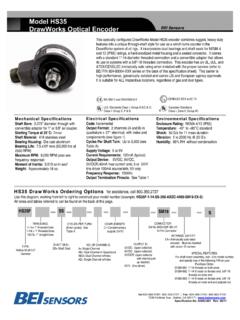
2 28V/OC NPN Open Collector, 80mA sink Protection Level Supply lines protected against over voltage to 60 volts and reverse voltage Tristate Outputs Available as S Special Feature ELECTRICAL SPECIFICATIONS MECHANICAL SPECIFICATIONS Package dimensions are mm high by 99 mm wide by mm thick. The package mounts to a DIN rail type EN 50 022 (35mm X ). A length of DIN rail is supplied with each MODULE . The MODULE simply snaps directly to the DIN rail and is ready to use. mm ( inches) mm ( inches) 99 mm POWER: The optical isolator can accommodate standard operating voltages from 5 to 28 VDC. It should never be connected directly to AC power mains. The MODULE draws approximately 75 mA and a green LED indicates the unit is powered. The optical isolator MODULE does not provide power to the encoder. Any encoders used in conjunction with this MODULE must be connected to their own power.
3 SIGNAL: Specifying an optical isolator MODULE requires knowledge of three system parameters: the DC supply voltage available in the system; the encoder output type (logic levels and driver type); and the input signal specifications of the receiving electronics. This is a versatile interface between an incremental encoder and receiving electronics. It accepts single ended or differential inputs and provides single ended or differential outputs in either an open collector or line driver configuration. It accommodates all standard operating voltages from 5 to 28 VDC. Up to eight Optical Isolator Modules can be daisy-chained to provide multiple, simultaneous outputs to controllers or PLC s. This Optical Isolator can help clean up noisy signals by converting to a different line driver output. It has a 1 MHz throughput capability and can be used wherever a fast, optically isolated interface is required.
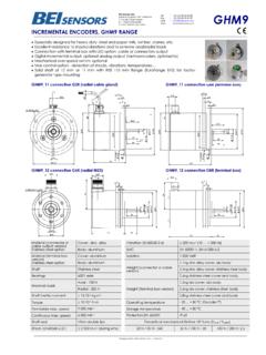
4 Tel: 805-968-0782/800-350-2727 | Fax: 805-968-3154/ 800-960-2726 | 7230 Hollister Ave, Goleta, CA 93117-2807| Specification No. 02125-001 Rev 0713 Differential Line Driver Encoder signals from 5 VDC to 24 VDC (must specify the voltage when ordering) This is the preferred type of encoder output as it has the best noise immunity. Connect each encoder signal to its like optical isolator input (A to A, A/ to A/, etc). Single Ended Line Driver Encoder signal from 5 VDC to 24 VDC (must specify the voltage when ordering) Connect encoder output A to optical isolator MODULE input channel A, B to B and Z to Z. Connect the A/, B/, and Z/ inputs of the optical isolator to circuit common of the encoder supply. Single ended operation is limited to shorter cable runs and is more susceptible to noise. CONNECTION INSTRUCTIONS #1 Z Z/ No Connection No Connection ENCODER B/ B A/ A CONTROLLER A A/ B B/ Z Z/ Vs, 5V to 28V 0V, Power Common A A A/ A/ B B B/ B/ Z Z Z/ Z/ +V 0V A A/ B B/ Z/ Z +V 0V REG VS 0V Optical Isolator Encoder Differential Line Driver Output Figure 1 Standard Connection to Optical Isolator MODULE CONNECTION INSTRUCTIONS #2 A A A/ B B B/ Z Z Z/ +V 0V A A/ B B/ Z/ Z +V 0V REG VS 0V Optical Isolator Encoder Single Ended Line Driver Output Figure 2 Connection Diagram Single Ended Line Driver Encoder Supply Z No Connection Connect A/, B/, Z/ to Encoder Circuit Common ENCODER B A CONTROLLER A A/ B B/ Z Z/ Vs, 5V to 28V 0V, Power Common No Connection Tel: 805-968-0782/800-350-2727 | Fax: 805-968-3154/ 800-960-2726 | 7230 Hollister Ave, Goleta, CA 93117-2807| Specification No.
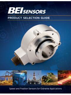
5 02125-001 Rev 0713 Open Collector with or without Internal Pull-up Resistors Encoder NPN (sinking) outputs. Connect encoder output A to optical isolator MODULE input A/, B to B/ and Z to Z/. Connect the A, B, and Z inputs of the optical isolator to the auxiliary output terminal on the optical isolator MODULE for 5V MODULE and to higher voltage when specified by MODULE model and part number. This connection results in a logic inversion within the optical isolator MODULE . To compensate for the logic reversal, swap A for A/, B for B/, and Z for Z/ at the optical isolator outputs. Example 1: Resolve an electrical conflict between encoder output and receiving electronics Sometimes system constraints result in an incompatibility between the encoder output and the receiving electronics or the cabling. A typical symptom of this problem is missed or intermittent counts.
6 As an example, a single-ended TTL receiver that is more than 20 feet from the encoder may not be able to compensate for the signal attenuation and ringing caused by the encoder cabling. An optical isolator MODULE installed near the receiver as shown in Figure 4 can receive the signal, rejecting the cable effects and produce a signal compatible with the input device. CONNECTION INSTRUCTIONS #3 Z Encoder Circuit Common ENCODER B A CONTROLLER A/ A B/ B Z/ Z Vs, 5V to 28V 0V, Power Common +5 Output A or A/ A A/ B or B/ B B/ Z or Z/ Z Z/ +V 0V A A/ B B/ Z/ Z +V 0V REG VS 0V Optical Isolator Encoder Open Collector Output Figure 3 Connection Diagram Open Collector to Optical MODULE Optical Regulation Power Supply AUX 5V Uses for Optical Isolator MODULE Optical Isolator MODULE TTL Single-Ended Receiver > 20 < 6 FIGURE 4 LONG CABLE RUN TO SINGLE ENDED INPUT To 5 AUX for 5V MODULE .
7 To 12-15 for 24V dependent on specified MODULE input voltage. Tel: 805-968-0782/800-350-2727 | Fax: 805-968-3154/ 800-960-2726 | 7230 Hollister Ave, Goleta, CA 93117-2807| Specification No. 02125-001 Rev 0713 Example 2: Signal Splitter The optical isolator can be used to connect a single encoder to multiple devices. Optical isolator can be used to split an encoder output to drive up the 8 devices as shown in Figure 5. One optical isolator MODULE is used to drive each receiver. Optical isolator modules can be specified with outputs to match receiver inputs; an encoder signal can be split to drive a differential TTL input with one MODULE , a 12 V line driver with another MODULE and provide an open collector, NPN signal with another MODULE . * Also see the BEI Encoder Signal Broadcaster MODULE on page 5 for this application* Example 3: Repeater On extremely long cable runs (greater than 500 feet), an optical isolator MODULE may be needed as a mid-point repeater to receive, amplify and re-broadcast the signal.
8 An example is illustrated in Figure 6. Opto Isolator 60001 - 003 FIGURE 5 CONNECTION DIAGRAM FOR MULTIPLE, NON - COMPATIBLE RECEIVERS Opto Isolator 60001 - 003 Opto Isolator 60001 - 003 Opto Isolator 60001 - 002 Encoder Supply V 5V Logic Line Driver 5V Output Maximum of 8 Optical Isolator Modules 24V Supply 24V Logic 12 V Supply 12 V Logic 5 V Supply 5 V Logic 24V Supply 5 V Logic Optical Isolator MODULE PLC 500 500 FIGURE 6 REPEATER FOR VERY LONG CABLE RUNS Tel: 805-968-0782/800-350-2727 | Fax: 805-968-3154/ 800-960-2726 | 7230 Hollister Ave, Goleta, CA 93117-2807| Specification No. 02125-001 Rev 0713 To find the correct optical isolator for your application, look in column 1 for the logic voltage of your encoder. Then choose the correct row in column 2 that describes the type of output from the isolator that is compatible with your receiving electronics.
9 Read across to columns 3 and 4 to find the MODULE and part number of the correct optical isolator. (1) Encoder Output Logic Level Voltage (2) Optical Isolator Output Logic Level Voltage (3) Model Number (4) Part Number 5V Vout = Vin Vout = 5V Vout = OC EM-DR1-IC-5-TB-28V/V EM-DR1-IC-5-TB-28V/5 EM-DR1-IC-5-TB-28V/OC 60001-003 60001-002 60001-004 12-15V Vout = Vin Vout = 5V Vout = OC EM-DR1-IC-15-TB-28V/V EM-DR1-IC-15-TB-28V/5 EM-DR1-IC-15-TB-28V/OC 60001-008 60001-012 60001-014 24V Vout = Vin Vout = 5V Vout = OC EM-DR1-IC-24-TB-28V/V EM-DR1-IC-24-TB-28V/5 EM-DR1-IC-24-TB-28V/OC 60001-010 60001-011 60001-013 Optical Isolator Selection Table Additional Modules and Accessories ENCODER SIGNAL BROADCASTER MODULE Accepts standard incremental encoder inputs and can broadcast up to four encoder signals to four independent devices. Each of the broadcast signals are optically isolated eliminating ground loops.
10 POWER SUPPLY With a wide range of acceptable input voltages (AC and DC) this DIN Rail mountable power supply is usable in virtually all industrial applications worldwide. It has built in surge protection to reduce faults due to transients and it has 100% reserve capacity for startup and overload conditions. CABLE AND CABLE ASSEMBLIES Cable reels for your own custom wiring requirements or cable assemblies are available, using high quality custom BEI standard cable consisting of four, low capacitance shielded twisted pairs with an overall shield, extra large conductors for power, and signal ground; all within an abrasion-resistant PVC jacket. Cable Reels 100 ft. reel Part No. 37048-003-100 500 ft. reel Part No. 37048-003-500 Cable Assemblies Part Nos. for MS3106F14S-6S Mating Connector 10 ft. # 31186-1410 20 ft. # 31186-1420 30ft. # 31186-1430 Part Nos.