Transcription of ELP 7.5-10 TON HEAT PUMPS HEAT PUMP …
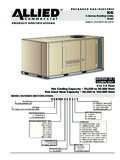
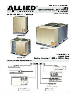
1 heat PUMP outdoor UNITS. ELP. T-SERIES COMMERCIAL SPLIT SYSTEMS. R-410A - 60 HZ. Bulletin No. ELP-090-120 (3/2018). P R O D U C T S P E C I F I C AT I O N S. EER up to to 10 Tons Cooling Capacity - 89,000 to 115,000 Btuh Heating Capacity - 88,000 to 114,000 Btuh MODEL NUMBER IDENTIFICATION. EL P 120 S 4 S T 1 Y. Brand/Family Voltage EL = E-Series Product Line Y = 208/230V-3 phase-60hz G = 460V-3 phase-60hz J = 575V-3 phase-60hz unit Type P = Split System heat Pump Minor Design Sequence 1 = 1st Revision Nominal Cooling Capacity Tons 2 = 2nd Revision 090 = Tons 3 = 3rd Revision 120 = 10 Tons Cooling Efficiency Part Load Capability S = Standard Efficiency T = Two Stage Compressor Refrigerant Type Refrigerant Circuits 4 = R 410A S = Single Circuit FEATURES AND BENEFITS.
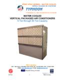
2 B. C. I. L. D. F E. A. H K. G. J. 120 Model (090 Model Similar). APPLICATIONS. CONTENTS. AHRI System 8 heat PUMPS are available in and 10 ton nominal sizes. 9. Electrical 6 Matching air handlers provide a wide range of cooling capacities and applications. See AHRI Ratings tables. Features And 2. Model Number 1 See Air Handlers sections for air handler data. Options / Accessories .. 7 Units shipped completely factory assembled, piped, and 10 wired. Each unit is test operated at the factory insuring proper operation.
3 Sound Data .. 6. Specifications .. 6 Installer must set heat pump, connect refrigerant lines, add refrigerant charge and make electrical connections unit 8. to complete job. Weight Data .. 8. APPROVALS. All units tested in an ETL certified environmental testing facility. AHRI Certified to AHRI Standard 340/360-2015. Sound tested in accordance with test conditions EQUIPMENT WARRANTY included in AHRI Standard 270 or 370. Units and components within are bonded for grounding Compressor - Limited warranty for five years in non- to meet safety standards for servicing required by UL, residential applications.
4 ULC, NEC and CEC. All other covered components - One year in non- All units are ETL listed. residential applications. ISO 9001 Registered Manufacturing Quality System. Refer to Allied Equipment Limited Warranty certificate for specific details. All units meet two-stage requirements of ASHRAE , IECC 2015, and California Code of Regulations, Title 24. ELP to 10 Ton heat PUMPS / Page 2. FEATURES AND BENEFITS. REFRIGERATION SYSTEM G Refrigerant Lines and Service Valves Refrigerant Sweat connections. Units operate with chlorine-free,ozone friendly, R-410A Fully serviceable liquid and suction line service valves (field furnished).
5 Provide complete service access to refrigerant system. Suction valve can be fully shut off, while liquid valve B outdoor Coil Fan(s) can be front seated to manage refrigerant charge while Dual direct drive fan(s) moves large volumes of air servicing system. uniformly through entire condenser coil(s) for high refrigerant cooling capacity. Refrigerant lines and field wiring inlets are located in one central area of the unit cabinet. Upward discharge of air reduces operating sound levels and prevents damage to lawns, shrubs, and walkways.
6 H COMPRESSORS. Fan motors are totally enclosed, overload protected and All models feature a single two-stage scroll compressor. equipped with a rain shield. Compressor features high efficiency with uniform Fan service access is accomplished by removal of fan suction flow, constant discharge flow and high guards. volumetric efficiency and quiet operation. Compressor consists of two involute spiral scrolls C Copper Tube/Enhanced Fin Coil(s) matched together to generate a series of crescent ELP090S has a single U shaped coil.
7 Shaped gas pockets between them. ELP120S has two L shaped coils. During compression, one scroll remains stationary while Coils are constructed of precisely spaced ripple-edge the other scroll orbits around it. aluminum fins machine fitted to seamless copper tubes. Gas is drawn into the outer pocket, the pocket is sealed Lanced fins provide maximum exposure of fin surface to as the scroll rotates. air stream resulting in excellent heat transfer. As the spiral movement continues, gas pockets are Fins equipped with collars that grip tubing for maximum pushed to the center of the scrolls.
8 Volume between the contact area. pockets is simultaneously reduced. Flared shoulder tubing connections and machine brazed When pocket reaches the center, gas is now high silver soldering provide tight, leakproof joints. pressure and is forced out of a port located in the center Long life copper tubing is corrosion-resistant and easy of the fixed scrolls. to field service. During compression, several pockets are compressed Thoroughly factory tested under high pressure to ensure simultaneously resulting in a smooth continuous leakproof construction.
9 Compression cycle. Completely accessible for cleaning. Continuous flank contact, maintained by centrifugal force, minimizes gas leakage and maximizes efficiency. D Reversing Valve Scroll compressor is tolerant to the effects of slugging Factory installed 4-way reversing valve provides rapid change in refrigerant flow direction resulting in quick and contaminants. If this occurs, scrolls separate, changeover from cooling to heating and vice-versa. allowing liquid or contaminants to be worked toward the center and discharged.
10 Valve operates on pressure differential between outdoor unit and indoor unit . Low gas pulses during compression reduces operational sound levels. E High Pressure Switch Compressor motor is internally protected from Shuts off unit if abnormal operating conditions cause excessive current and temperature. discharge pressure to rise above setting. Compressor is installed in the unit on resilient rubber Protects the compressor from excessive condensing mounts for vibration free operation. pressure. Manual reset. F Loss of Charge Switch Provides loss of charge and freeze-up protection.