Transcription of Energi Savr NodeTM 0-10 V / SoftSwitch …
1 Energi Savr NodeTM 0-10V / SoftSwitch installation GuideLutron | 1 Energi Savr NodeTM 0-10 V / SoftSwitch | installation GuideControl Panel RatingsControl Power: 120-277 V 50/60 Hz ALoad Inputs: 120-277 V 50/60 HzOutput: 0-10 V: 50 mA sink per zone (QSN-4T16-S only) SoftSwitch : 120-277 V 16 A per output HP @ 120 V HP @ 277 VOperating environment: 32 F to 104 F (0 C to 40 C)Maximum humidity: 90% non-condensingThermal dissipation: 40 BTU/hrInput Groups: 20 V 65 mA per groupQS link: 24 V 14 PDU (Power Draw Units) 432 mAModel number overviewQSN-4T16-S ( Energi Savr Node for 0-10 V)QSN-4S16-S ( SoftSwitch Energi Savr Node)QSN: Energi Savr Node4T: 4 output zones, 0-10 V fixture controller4S: 4 output zones, SoftSwitch16: 16 A switched outputsS: Surface mountPlease read this guide before PageRatings and Model number overview.
2 1 Product ..3 Control power wiring ..3 Load wiring ..4 Input wiring ..6 Contact closure inputs ..7QS link wiring ..8 Applications ..10 Out of box functionality ..10 Normal operation ..11QS link input(s) setup ..11 Troubleshooting ..11 Warranty ..12 Contact information ..12 System ExampleProgramming guide available at : linkControl Power120-277 V4 Load Input Feeds120-277 V4 0-10 V Channels(QSN-4T16-S only)Emergency Contact Closure InputContact Closure Input4 Switched Load Outputs (16 A SoftSwitch 120-277 V)Wireless CommunicationWired Daylight Sensors (up to 4)2 Wired Daylight Sensors (up to 4)1,2 Wired Occupancy Sensors (up to 4)Wired Occupancy Sensors (up to 4)1 Wired Wallstation or IR receivers (up to 4)Wired Wallstation or IR Receivers (up to 4)1 NEC Class 2/PELV Dry Contact Switch (up to 4) (by others)
3 IR TransmitterIR Transmitter Notes: 1 Up to 4 wired sensors total (of any type).2 The maximum number of daylight sensors (wired and wireless) that an Energi Savr Node unit can support is four (1 per zone).QSM (new!)seeTouch QS WallstationESN Programming InterfaceRadio Powr SavrTM Occupancy Sensor (up to 10 per QSM)Radio Powr SavrTM Daylight Sensor (up to 10 per QSM)2 Pico Wireless Controller (up to 10 per QSM) Energi Savr NodeTM 0-10V / SoftSwitch installation GuideLutron | 2 Energi Savr NodeTM 0-10 V / SoftSwitch | installation GuideProduct overviewAn Energi Savr Node system consists of an Energi Savr Node unit, output loads, sensors, keypads, and QS interface devices.
4 The diagram on the previous page shows a typical system topology. All lighting loads and Energi Savr Node units are powered by line voltage. The Energi Savr Node unit is limited to: 4 lutron daylight sensors (models: EC-DIR-WH) 4 lutron occupant sensors (models: lutron LOS series) 4 lutron infrared (IR) receivers (models: EC-DIR-WH, EC-IR-WH, CC-1 BRL-WH, CC-4 BRL-WH) 4 NEC Class 2/PELV dry contact switch inputs 1 contact closure input 1 emergency contact closure input (defaults to Emergency Mode in the absence of a contact closure across the input) The QS Link can have up to 100 zones and 100 devices.
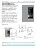
5 The Energi Savr Node unit counts as 1 device and 4 zones on the QS link. In a system with multiple Energi Savr Node units on a QS link, a maximum of 100 daylight sensors, 100 occupancy sensors, 100 IR receivers, and 100 Pico wireless controllers are permitted. The Energi Savr Node unit supplies up to 14 Power Draw Units (PDUs) for powering accessory QS devices. Refer to accessory device documentation for power draw to the following step-by-step guide for proper Energi Savr Node unit overviewQS LinkContact Closure Inputs0-10 V Channels(QSN-4T16-S only)Input GroupsControl powerInput power and switched outputs to loads (4 zones)Zone 1 Zone 2 Zone 3 Zone 4 Zone 1 Zone 2 Zone 3 Zone 4 Energi Savr NodeTM 0-10V / SoftSwitch installation GuideLutron | 3 Energi Savr NodeTM 0-10 V / SoftSwitch | installation GuideStep-by-step installation instructionsStep 1: Mounting the unitNote.
6 Mount the Energi Savr Node unit in a position where it can be easily located and accessed if service or troubleshooting is necessary. Remove metal outer panel cover. Remove internal plastic line voltage shield. For indoor use only! NEMA, Type 1 enclosure, IP20. Mount panel where audible noise is acceptable (internal relays click). Mount panel so line voltage wiring is at least 6 ft ( m) from audio or electronic equipment and associated wiring (prevents radio frequency interference). Install in accordance with all national and local electrical DimensionsAll dimensions shown as inches (mm)Control Power ( ) ( ) ( ) 4 ( ) ( ) ( ) ( ) ( ) ( ) ( ) ( ) ( ) ( ) ( ) ( )Step 2: Control power wiringThe Energi Savr Node unit operates at 120-277 V.
7 Use the following instructions to wire line voltage to power the Energi Savr Node ! Danger of Shock. May result in serious injury or death. DO NOT WIRE WHEN LIVE! Switch off power to all power feeds via circuit breaker before wiring or servicing the Energi Savr Node and LEDs in the unit are used for programming and troubleshooting. If wiring is exposed when accessing buttons and LEDs, the unit must be accessed by a certified electrician, following local codes. 1. Remove metal outer panel Remove internal plastic line voltage Use 14 AWG to 12 AWG ( mm2 to mm2) conductors (de-pending on breaker rating) to feed the control power wiring.
8 The Energi Savr Node unit draws less than Wire the line voltage cables to the terminals labeled H (Hot) and N (Neutral). A two-position terminal block is The Energi Savr Node unit is grounded through the ground bar. Attach the ground Reinstall internal plastic line voltage Turn on the circuit breaker to power up the Energi Savr Node unit. The Wired LED on the Energi Savr Node unit will light when properly energized. If the LED does not light, turn off power, then check the control power Turn power Power Wiring: Two (2) 14 AWG to 12 AWG ( mm2 to mm2) Strip length: 3/8 in ( mm) Torque: 7 in-( N m)Neutral (N)Hot (H)GroundLine Voltage ShieldEnergi Savr NodeTM 0-10V / SoftSwitch installation GuideLutron | 4 Energi Savr NodeTM 0-10 V / SoftSwitch | installation GuideStep 3: Load wiringThe Energi Savr Node unit operates at 120-277 V.
9 Use the following instructions to wire line voltage loads to the Energi Savr Node ! Danger of Shock. May result in serious injury or death. DO NOT WIRE WHEN LIVE! Switch off power to all power feeds via circuit breaker before wiring or servicing the Energi Savr Node Energi Savr Node unit is a feed-through device. This means that each switched output needs the Line and Load wires. THERE IS NO INTERNAL CONNECTION BETWEEN THE CONTROL POWER TO THE UNIT AND THE SWITCHED Switching:120-277 V0-10 V Zones:(QSN-4T16-S only)Feed-Through Wiring Example 1 4 Circuits, Multiple FeedsSwitched Hot (1B)Hot Feed (1A)Hot Feed (2A)Hot Feed (3A)Hot Feed (4A)Switched Hot (2B)Switched Hot (3B)Switched Hot (4B)Ground BarNeutral WiresDistribution PanelLOADLOADLOADLOAD0-10 V Wiring (QSN-4T16-S only) 20 AWG to 12 AWG ( mm2 to mm2) Strip length: 1/4 in (6 mm) Torque.
10 5 in-lbs ( N m) Connect only NEC Class 2/PELV circuits or connect only non-NEC Class 2/PELV circuits to 0-10 V zones 1-4. 0-10 V zones 1-4 are not isolated from each other. Negative ( ) terminals are not internally connected to each other both positive (+) and negative ( ) connections must be made. Follow all national and local codes for separation Wiring: Two (2) 14 AWG to 12 AWG ( mm2 to mm2) Strip length: 3/8 in ( mm) Torque: 7 in-lbs ( N m)0-10 V Wiring(QSN-4T16-S only)HotHotHotHotNeutralNeutralNeutralNe utralGroundGroundEnergi Savr NodeTM 0-10V / SoftSwitch installation GuideLutron | 5 Energi Savr NodeTM 0-10 V / SoftSwitch | installation GuideLoad Wiring (continued)Feed-Through Wiring Example 2 4 Circuits, Single FeedZone Switching:120-277 V0-10 V Zones.