Transcription of Energy efficiency and fuel consumption of fuel cells ...
1 Energy efficiency and fuel consumption of fuel cells powered test railway vehicle , , Railway technical research institute , tokyo , JAPAN 1. Abstract For the purpose of an environmental burden reduction and an improvement of Energy efficiency , we (RTRI) have been developing the railway vehicle powered by fuel cells (FC) since the year 2001. We made FC system for vehicle traction and high-pressurized hydrogen cylinder system experimentally, and constructed the FC test vehicle that can run as one car alone. We executed the running tests in our test facilities and evaluated FC Energy efficiency and fuel consumption with the running data obtained from these running tests.
2 Then, because our test vehicle could not run on a commercial line, we evaluated Energy efficiency and fuel consumption under the condition of the commercial line by the running simulation. 2. Introduction Presently, diesel cars are running with engines in un-electrified sections and it is connected to the fossil fuel dry up problem. In addition, it has such problems as low Energy efficiency , emission of CO2 and NOx, heavy noise and vibration. With the consideration on these problems, we paid our attention on FC that generates powers with high efficiency from hydrogen, and started the study to use FC as the power supply for railway vehicle traction in the year 2001.
3 FC drains only the water produced by FC s internal reaction and a part of air that does not contribute to the reaction. So, we can use FC as a very clean power supply. In addition, by use of regenerative hydrogen Energy , it is also a measure against fossil fuel dry up problem. In the year 2005, we made experimentally 100 kW class PEMFC (proton electrode membrane type of FC) for railway vehicle traction and 35 Mpa high-pressurized hydrogen cylinder, and installed them in the test vehicle and prepared the test vehicle powered by FC that can run as one car alone. In the year 2006, we executed the running test in our test facilities and confirmed that test vehicle could be driven by FC.
4 With the data obtained from these running tests, we calculated our FC s Energy efficiency and verified the adequacy of FC Energy efficiency of 40% that we had used in our running simulation. In addition, we also calculated fuel consumption that could be a barometer of fuel on board and evaluated it under various running conditions. As our test vehicle does not have the commercial registration, it is difficult to make our test vehicle run in the commercial line. Therefore, we executed the running simulation with commercial line s data and calculated Energy efficiency and fuel consumption . In addition, we evaluated by simulation the advancement of Energy efficiency and the reduction of fuel consumption quantitatively in the case of utilizing regenerative Energy .
5 We report the details in the following. 3. Characteristics of PEMFC Firstly, we will explain the structure and the principle of electric generation of PEMFC below (Fig 1). PEMFC has a thin membrane covered by platinum on the both surfaces. When hydrogen is supplied to one side and oxygen, to the other side of this membrane, hydrogen becomes hydrogen proton and electron by the platinum s catalysis. Only hydrogen proton passes through the membrane and moves to the oxygen side. When the external load is connected to the electrode installed on each side of membrane, electron moves to the oxygen side through it. Finally, oxygen, hydrogen proton, electron are combined to become water on the oxygen side and drain out.
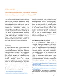
6 By this electron s move, electric current flows, and we can use FC as a power supply. Namely, PEMFC generates powers by the chemical reaction of hydrogen and oxygen, which can be taken from an air. In addition, the operational temperature of PEMFC is lower than other types of FC and it is possible to start up almost instantly. Therefore, PEMFC is noted as the power supply for mobile object such as automobile that are inquired the limited space of installation and the quick start-up time and so on. Fig 1 Principle of electric generation of PEMFC 4. 100kW class PEMFC system We explain below the FC system that was made experimentally. Our FC system that we made experimentally is based on stationary system and is downsized for installation in the railway vehicle [1].
7 This system can output 100kW class powers needed for one vehicle traction. The exterior of the system is shown in Fig and the specification, in Table 1. Fig Exterior of 100kW class PEMFC system Table 1 Specification of 100kW class PEMFC system Rated power 120 kW (Net), 150 kW (Gross) Output voltage 600 V (rated), 850 V (no load) Load current 200 A (Net), 250 A (Gross) Mass 1,650 kg Dimension m (L) m (W) m (H) Stack composition 8 series Start up time About 1min30sec We explain the major characteristics of our FC system below.
8 The system can generate powers independently. Internal auxiliary powers of FC are supplied by self-generated powers. The system generates powers following a railway s fluctuated loads. The system achieves a hydrogen use rate of more than 99% by hydrogen recycle function. The system has the function to recycle the water produced by FC s internal reactions. We executed the bench test and verified that our system satisfied the requirements of the specification nearly (Fig ). 0200400600800100012001400050 100 150 200 Load Current[A]Output Voltage[V]020406080100120140 Output Power[kW]Output VoltageOutput PowerOutput Power 120kW(185A, 650V)650V Fig Bench test result 5.
9 Composition of FC test vehicle Installation of equipments 1. FC system We installed FC system at the center of our test train so as to make us be able to check FC s operational state all the time. 2. High pressurized hydrogen cylinder system We installed hydrogen cylinder system under the floor of our test vehicle so the hydrogen not to be remained in the test vehicle when it leaks. This system consists of four cylinders and one cylinder can contain hydrogen high pressurized with 35 Mpa. 3. Inverter for vehicle traction We installed the Inverter for vehicle traction at the back of test vehicle and fixed the control device that can change running parameters.
10 At this time, the vehicle auxiliary powers (for air conditioner, compressor, room light) were supplied from the contact wire, but we are planning to build up FC powers so as the vehicle auxiliary powers can be supplied from FC powers in the future. By installation of these equipments, we composed the FC test vehicle that could run as one car alone (Fig ). Fig FC test vehicle Composition of main circuit We explain the composition of main circuit of FC test vehicle in Fig Fig Composition of main circuit At this time, in order to obtain the characteristic of FC when we use only it for vehicle traction without Energy storage device, we connected FC directly to main circuit.