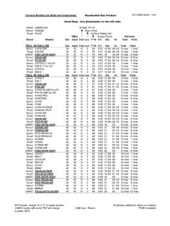
Transcription of ENERGY SMART TROUBLESHOOTING GUIDE - …
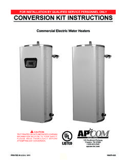
1 1 ENERGY SMART TROUBLESHOOTING GUIDETABLE OF CONTENTS:COMPONENTS/BOARD LAYOUT .. 2NO HOT WATER .. 31 FLASH (GREEN DIAGNOSTIC LIGHT) .. 42 FLASHES (GREEN DIAGNOSTIC LIGHT) .. 53 FLASHES (GREEN DIAGNOSTIC LIGHT) .. 64 FLASHES (GREEN DIAGNOSTIC LIGHT) .. 75 FLASHES (GREEN DIAGNOSTIC LIGHT) .. 86 FLASHES (GREEN DIAGNOSTIC LIGHT ) .. 9 THERMISTOR RESISTANCE/TEMPERATURE CHART .. 1055100532 COMPONENTS/BOARD LAYOUT7889101112131415 TOD BOARD78109111213 UTEC CONTROL BOX CONTROL THERMISTOR ELEMENT POWER WIRES ELEMENT ELEMENT JUMPER WIRE (BLACK) POWER WIRES (RED & BLACK) BOTTOM ELEMENT WIRE (ORANGE) TOP ELEMENT WIRE (YELLOW) COMMON ELEMENT POWER WIRE (BLUE) TEMPERATURE MODE THERMISTOR BUTTON (TOD BOARD ONLY)14125643 TOP ELEMENT SHOWN3NO HOT WATERF lash Code:1 Flash, go to page Flashes, go to page Flashes, go to page Flashes, go to page Flashes, go to page Flashes, go to page fl ash and clicking sound, go to page the green light fl ashing?
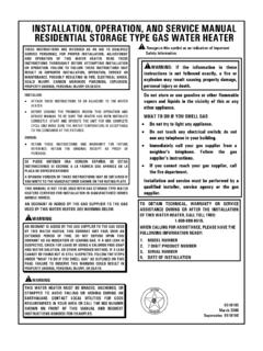
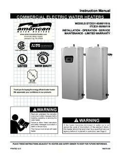
2 Is the green light on?Remove the control box cover and check the voltage from the red and black wires on top of relays. See Figure 1A & voltage control supply voltage at circuit breaker or fuse V240 V0 VFIGURE 1A - TOD BOARDFIGURE 1B - UTEC BOARDE nsure temperature control is set to a temperature above 115 F. Ensure operating mode is in EnergySmart mode or SMART Mode. Allow heater time to recover from heavy hot water use or change in operating FLASH (GREEN DIAGNOSTIC LIGHT)Unit power has been applied to the heater prior to fi lling with the nearest hot water faucet, and fi ll the water heater until a steady stream of water fl ows out of the faucet. Once the water heater is completely fi lled, then shut-off the control the heater. UTEC boards, turn the power off then back on. TOD boards, press the reset button on the control box. Wait 10 minutes. Is the green diagnostic light still fl ashing 1 time?Repeat this process 3 times. Is this the 3rd try?
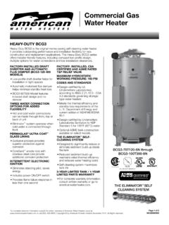
3 YESNONOYES52 FLASH (GREEN DIAGNOSTIC LIGHT)Turn off power to the heater, and remove the control box cover. See page 2. Using an ohm meter, check resistance between the blue and yellow wire connections (top element) and the orange and blue wire connections (lower element). Are readings between 5-25 ohms?Replace control water heater has reacted to an indicated high water temperature and shut the thermistor plug from the control board. Using an ohm meter measure resistance between the red wires in the thermistor plug, then measure the resistance between the two black wires in the plug. See fi gure 2. Measure the water temperature at a nearby hot water faucet. Using the chart on page 10, compare the measured resistance values with the measured temperature value. Are they within range according to the chart?Check position of wires on (left to right): black, orange, yellow, blue, & red. See page (left to right): yellow, orange, red, black, & blue.
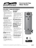
4 See page the wires in the correct order?Replace the defective element(s).Replace the wiring order and replace control cover. Turn the power back 2 - MEASURING THERMISTORS63 FLASH (GREEN DIAGNOSTIC LIGHT)Indicates thermistors are not operating off power to the heater, and remove the control box cover. See page 2. Ensure thermistor plug is seated tightly and correctly oriented. Are the thermistor wires damaged or shorted to the tank?If TOD board, replace thermistor and control board. If UTEC board, replace just the thermsitor. Restore power and wait 10 minutes. Still getting 3 fl ash code?Correct orientation of the thermistor plug and replace control cover. See page 2. Restore power. Still fl ashing 3 times?Replace the control board. Unit the thermistor plug from the control board. Using an ohm meter measure resistance between the red wires in the thermistor plug, then measure the resistance between the two black wires in the plug. See fi gure 3.
5 Measure the water temperature at a nearby hot water faucet. Using the chart on page 10, compare the measured resistance values with the measured temperature value. Are they within range according to the chart?FIGURE 3 - MEASURING THERMISTORS74 FLASH (GREEN DIAGNOSTIC LIGHT)The control board is sensing the upper element is off power to the water heater and remove the control box cover. See page 2. Inspect the yellow and blue wires connected to the relays. Do they appear to be damaged?Using an ohm meter measure resistance between the yellow and blue wires connected to the relays. Is the resistance 5 - 25 ohms?Is the heater connected to a recirculating or heating system? Disconnect the water heater from the power turned off to the heater replace the upper element. Re-attach the control box cover, and restore power to the water the control board. The board replacement kit includes replacement yellow and blue wires with new connectors. See Figure for hidden leaks in hot water system, possibly under a slab fl oor.
6 Is there a leak?Repair leak and reset 485 FLASH (GREEN DIAGNOSTIC LIGHT)The control board is sensing the lower element is off power to the water heater and remove the control box cover. See page 2. Inspect the orange and blue wires connected to the relays. Do they appear to be damaged?Using an ohm meter measure resistance between the orange and blue wires connected to the relays. Is the resistance 5 - 25 ohms?Is the heater connected to a recirculating or heating system? Disconnect the water heater from the the control board. The board replacement kit includes replacement orange and blue wires with new connectors. See Figure leak and reset for hidden leaks in hot water system, possibly under a slab fl oor. Is there a leak?With power turned off to the heater replace the lower element. Re-attach the control box cover, and restore power to the water 596 FLASH (GREEN DIAGNOSTIC LIGHT)The water heater has locked out due to a malfunction in the control the unit by turning off power and waiting 10 minutes.
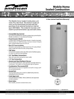
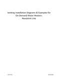
7 Is the green light still fl ashing 6 times?The water heater should be ok. However, if the 6 fl ash lock-out should occur again. Replace the control control BOARDSG reen light continuously clicking and fl ashing?Replace the control BOARDS10 THERMISTOR RESISTANCE CHARTUSING THE CHART:Make sure power to the heater has been turned off before performing the following steps. Remove the control box cover and unplug the thermistor plug from the control board. See page 2. Using an ohm meter measure the resistance value between the two red wires in the thermistor plug, then measure the resistance value between the two black wires in the plug See Fig 6. Record the water temperature at a nearby hot water faucet. Using the recorded resistance values check to see if the heater is in the correct range. For example: In Fig. 6 the measured temperature is 129 F. Using the chart above a temperature reading of 129 F should have a resistance reading between 15K - 10K.
8 Figure 6 WATER TEMPERATUREOHMS80 F - 100 F50K - 20K 100 F - 120 F40K - 15K 120 F - 150 F30K - 5K