Transcription of ENGINEERING AND DESIGN - United States Army
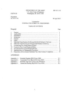
1 EM 1110-2-2104 30 November 2016 US Army Corpsof Engineers ENGINEERING AND DESIGN STRENGTH DESIGN FOR REINFORCED concrete HYDRAULIC STRUCTURES ENGINEER MANUAL EM 1110-2-2104 30 Nov 16 THIS PAGE INTENTIONALLY LEFT BLANK DEPARTMENT OF THE ARMY EM 1110-2-2104 Army Corps of Engineers CECW-CE Washington, DC 20314-1000 Manual No. 1110-2-2104 30 September 2016 ENGINEERING and DESIGN STRENGTH DESIGN FOR REINFORCED concrete HYDRAULIC STRUCTURES 1. Purpose. This manual provides guidance for designing reinforced concrete hydraulic structures by the strength DESIGN method. Plain concrete and prestressed concrete are not covered in this manual. 2. Applicability. This manual applies to all Headquarters, Army Corps of Engineers (HQUSACE)-commands having civil works responsibilities. The user of this Engineer Manual (EM) is responsible for seeking opportunities to incorporate the Environmental Operating Principles (EOPs) wherever possible.
2 A listing of the EOPs is available at: 3. Distribution Statement. Approved for public release; distribution is unlimited. 4. References. Appendix A lists required and related publications. 5. Discussion. This manual covers requirements for DESIGN of reinforced concrete hydraulic structures by the strength DESIGN method. It is applicable to all hydraulic structures. The manual contains provisions for DESIGN of structures that are satisfactory for both serviceability and ultimate strength. Industry DESIGN and construction standards have been adopted in this manual as applicable. FOR THE COMMANDER: 7 Appendices (See Table of Contents) COL, EN Chief of Staff This manual supersedes EM 1110-2-2104, dated 20 August 2003. 30 November 2016 EM 1110-2-2104 30 Nov 16 THIS PAGE INTENTIONALLY LEFT BLANK 2 DEPARTMENT OF THE ARMY EM 1110-2-2104 Army Corps of Engineers CECW-CE Washington, DC 20314-1000 Manual No.
3 1110-2-2104 30 November 2016 EXPIRES 31 MAY 2013 ENGINEERING and DESIGN STRENGTH DESIGN FOR REINFORCED concrete HYDRAULIC STRUCTURES TABLE OF CONTENTS Paragraph Page CHAPTER 1. Introduction 1-1 General Requirements.. 1-1 1-2 Computer Programs.. 1-2 Mandatory 1-2 CHAPTER 2. Details of reinforcement 2-1 Quality.. 2-1 2-1 Anchorage and Bar 2-1 Hooks and Bends.. 2-1 Bar 2-1 concrete Protection for reinforcement .. 2-1 Splicing.. 2-2 Temperature and Shrinkage reinforcement .. 2-3 concrete 2-5 reinforcement 2-5 Mandatory 2-7 CHAPTER 3. Strength and Serviceability Requirements 3-1 3-2 Required Strength.. 3-9 DESIGN Strength of reinforcement .. 3-12 reinforcement Limits.. 3-13 Control of Deflection and Cracking.. 3-13 i LIST OF FIGURES (CONTINUED) EM 1110-2-2104 30 Nov 16 Paragraph Page Minimum Thickness of Walls.
4 3-14 Mandatory 3-14 CHAPTER 4. Flexure and Axial Loads DESIGN Assumptions and General Requirements.. 4-1 Interaction Diagrams.. 4-2 Biaxial Bending and Axial Load for all 4-5 Mandatory 4-6 CHAPTER 5. Shear Shear 5-1 APPENDICES APPENDIX E Load Combinations for DESIGN of Typical Reinforced concrete Shear Strength for Cantilevered Walls.. 5-1 Shear Strength for Special Straight Members.. 5-1 Shear Strength for Curved Members.. 5-3 Mandatory 5-3 APPENDIX A APPENDIX B DESIGN Equations for Flexural and Axial APPENDIX C Investigation APPENDIX D DESIGN Examples ..D-1 Hydraulic APPENDIX F Commentary on Chapter APPENDIX G Acronyms and Abbreviations ..G-1 Figure 2-1. reinforcement Detailing at Moment Connections. LIST OF FIGURES 2-5 Figure 2-2. Typical Seismic reinforcement Details Olmsted L&D. 2-7 Figure 3-1.
5 Load Category versus Return Period. 3-3 Figure 4-1. Interaction Diagram with Illustrated Failure Modes. 4-3 Figure 4-2. Interaction Diagram with Strain Conditions Illustrated. 4-4 ii EM 1110-2-2104 30 Nov 16 LIST OF FIGURES (CONTINUED) Figure 5-1. Critical Sections for Shear in Cantilever L-Type Walls. 5-2 Figure B-1. Axial Compression and Flexure, Single reinforcement . B-1 Figure B-2. Axial Compression and Flexure, Double reinforcement . B-6 Figure B-3. Axial Tension and Flexure, Double reinforcement . B-11 Figure C-1. Diagram of Singly Reinforced Beam Cross Section, Strain, and Stress. C-1 Figure C-2. Slab with reinforcement on Both Faces with Diagram of Stress and Figure C-12. Flexural Strength When Both Bending Moments are Acting Figure D-1. Section of Stress for Singly Reinforced Member.
6 Strain. C-3 Figure C-3. General Interaction Diagram points and Given Cross Section. C-7 Figure C-4. Stress and Strain under Pure Flexure. C-8 Figure C-5. Stress and Strain under Maximum Axial Load. C-9 Figure C-6. Stress and Strain at Balanced Point. C-9 Figure C-7. Interaction Diagram for Combined Bending and Axial Forces. C-11 Figure C-8. Interaction Diagram produced in CGSI. C-12 Figure C-9. Cross Section of Column with 8 #6 bars. C-13 Figure C-10. Inputs for CGSI. C-14 Figure C-11. User Inputs for CGSI. C-15 Simultaneously. C-15 Figure C-13. Nominal Flexural Strength about the X-Axis. C-17 Figure C-14. Nominal Flexural Strength about the Y-Axis C-18 D-1 Figure D-2. Section of Stress and Strain for Doubly Reinforced Member. D-2 Figure D-3. Retaining Wall with Moment at the Base of Stem. D-5 Figure D-4. Retaining Wall with Moment at the Base of Stem Doubly Reinforced.
7 D-7 Figure D-5. Retaining Wall with Moment at the Base of Stem plus Axial Load. D-10 iii LIST OF TABLES (CONTINUED) EM 1110-2-2104 30 Nov 16 LIST OF FIGURES (CONTINUED) Figure D-6. Coastal Floodwall with Load Case Loads. D-13 Figure D-7. Rectangular Conduit. D-21 Figure D-8. Circular Conduit. D-22 Figure F-1-1. Reliability Concepts. F-8 LIST OF TABLES Table 2-1. Minimum Clear Distance from the Edge of the reinforcement to the Surface of the concrete . 2-2 Table 2-3. Minimum Shrinkage and Temperature reinforcement Ratios for Various Table C-1. Moment Capacity of a Beam with Tension Steel Only and of a Beam with Table 2-2. Longitudinal Stagger of Tension Butt Splices. 2-3 Joint Spacings. 2-4 the Addition of Compression Steel. C-6 Table D-1. Minimum Effective Depth. D-4 Table D-2.
8 DESIGN Example of Coastal Floodwall. D-12 Table D-3. Loads and Load Combinations in Accordance with Section D-13 Table D-4. Factored Loads for the Predetermined Governing Load Case C1B. D-15 Table D-5. Calculation of Moment per Bar Spacing along the Length of Wall. D-18 Table D-6. Factored Loads Determined Based on a Pile Spacing of 6 ft. D-19 Table E-1. Load Combinations for a Retaining Wall. E-1 Table E-2. Load combinations for an Inland Floodwall. E-2 Table E-3. Load combinations for a Coastal Floodwall. E-3 Table E-4. Load combinations for an Intake Tower. E-4 Table E-5. Load combinations for a Navigation Lock Wall. E-8 Table E-6. Load combinations for a Navigation Lock Gate Monolith. E-9 Table E-7. Load combinations for a Navigation Lock Approach Wall. E-11 iv EM 1110-2-2104 30 Nov 16 LIST OF TABLES (CONTINUED) Table E-8.
9 Load combinations for Spillway Approach Channel Walls. E-12 Table E-9. Load combinations for Spillway Chute Slab Walls. E-14 Table E-10. Load combinations for Spillway Stilling Basin Walls. E-15 Table F-1. Summary of Changes to this Manual since the 20 August 2003 Version. F-1 Table F-1-1. Trial Serviceability Designs. F-5 Table F-1-2. Target Reliability for 100-yr Service Life, . F-7 v EM 1110-2-2104 30 Nov 16 THIS PAGE INTENTIONALLY LEFT BLANK vi EM 1110-2-2104 30 Nov 16 CHAPTER 1 Introduction Background. Industry DESIGN and construction standards (American concrete Institute [ACI], American Association of State Highway and Transportation Officials [AASHTO], etc.) are adopted as applicable to provide safe, reliable, and cost effective hydraulic structures for civil works projects.
10 Reinforced concrete Hydraulic Structures (RCHS) are directly subjected to submergence, wave action, spray, icing or other severe climatic conditions, and sometimes to a chemically contaminated atmosphere. Satisfactory long-term service requires that the saturated concrete be highly resistant to deterioration due to daily or seasonal weather cycles and tidal fluctuations at coastal sites. The often relatively massive members of RCHS must have adequate density and impermeability, and must sustain minimal cracking for control of leakage and for control of corrosion of the reinforcement . Most RCHS are lightly reinforced structures ( reinforcement ratios less than 1%) composed of thick walls and slabs that have limited ductility compared to the fully ductile behavior of reinforced concrete buildings (in which reinforcement ratios are typically 1% or greater). Typical RCHS are: stilling basin slabs and walls; concrete lined channels; submerged features of powerhouses and pump stations; spillway piers; spray and training walls; floodwalls; submerged features of intake and outlet structures (towers, conduits and culverts); lock walls; guide and guard walls; and submerged retaining walls and other structures used for flood barriers, conveying or storing water, generating hydropower, water borne transportation, and for restoring the ecosystem.