Transcription of Engineering Bernoulli Equation
1 1 Engineering Bernoulli Equation R. Shankar Subramanian Department of Chemical and Biomolecular Engineering Clarkson University The Engineering Bernoulli Equation can be derived from the principle of conservation of energy. Several books provide such a derivation in detail. The interested student is encouraged to consult White (1) or Denn (2). Here, I have merely summarized the important forms of this Equation for your use in solving problems. Whenever you use this Equation , be sure to draw a sketch and clearly mark the datum from which heights are measured.
2 When setting a term to zero, indicate the reason for doing so. For example, when the free surface of the liquid in a tank is exposed to the atmosphere, or when it is issuing as a free jet into the atmosphere, the pressure at that location is set equal to zero gage. When liquid is taken out of a vessel through a pipe of cross - sectional area that is small compared with that of the vessel, the velocity of the free surface will be relatively small, and the kinetic energy term associated with that velocity can be set equal to zero without much error.
3 When the Engineering Bernoulli Equation is applied to fluid contained in a control volume fixed in space, typically the control volume has impenetrable boundaries, with the exception of one or more inlets and one or more outlets through which fluid enters and leaves the control volume. During passage of fluid through the control volume, mechanical work is irreversibly transformed by fluid friction into heat, leading to losses. Also, the fluid may operate a turbine, performing work on the blades of the machine, or work may be performed on the fluid by a pump.
4 These lead to shaft work, assumed by convention to be positive when performed by the fluid, and negative when performed on the fluid. Both losses and shaft work are included in the energy form of the Engineering Bernoulli Equation on the basis of unit mass of fluid flowing through. The two most common forms of the resulting Equation , assuming a single inlet and a single exit, are presented next. Energy Form Here is the energy form of the Engineering Bernoulli Equation . Each term has dimensions of energy per unit mass of fluid.
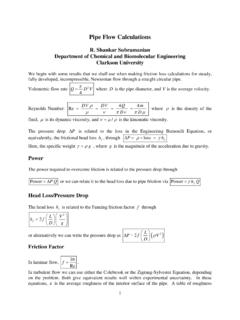
5 22loss22outoutininoutinsp VpVgzgzw + + =++ In the above Equation , p is pressure, which can be either absolute or gage, but should be in the same basis on both sides, represents the density of the fluid, assumed constant, V is the velocity of the fluid at the inlet/outlet, and z is the elevation about a datum that is specified. Note that it is only differences in elevation that matter, so that the choice of the datum for z is arbitrary. The symbol g stands for the magnitude of the acceleration due to gravity. 2 The term loss stands for losses per unit mass flowing through, while sw represents the shaft work done by the fluid per unit mass flowing through.
6 The form given above assumes flat velocity profiles across the inlet and exit, which is a reasonable approximation in turbulent flow. In laminar flow, the velocity distribution across the cross -section must be accommodated in the kinetic energy calculation. In that case, we use the average velocities at the inlet and exit, but multiply the kinetic energy terms on each side of the Engineering Bernoulli Equation by a correction factor that accounts for the variation of the kinetic energy of the fluid across the cross -section.
7 You can consult references (1) or (2) to learn how to calculate this correction factor. We express loss usually as a certain number (N) of velocity heads. In this case, loss = ()2/2NV. At other times, loss is expressed as a certain ()M head of fluid. In this case, loss = gM. Head Form The head form of the Engineering Bernoulli Equation is obtained by dividing the energy form throughout by the magnitude of the acceleration due to gravity,g. 22loss22outoutininsoutinp VpVwzzgggg + + = + + In this Equation , the symbol represents the specific weight of fluid.
8 G = We define the head developed by a pump as /pshwg= . Because the work term swis negative for a pump, the head developed by a pump ph is always positive. Loss is always positive. We define a head loss term as frictionlossfhhg==. Therefore, we can rewrite the head form of the Engineering Bernoulli Equation as 2222outoutininoutinfpp VpVzz hhgg + + = + + + Now, two examples are presented that will help you learn how to use the Engineering Bernoulli Equation in solving problems. In a third example, another use of the Engineering Bernoulli Equation is illustrated.
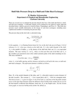
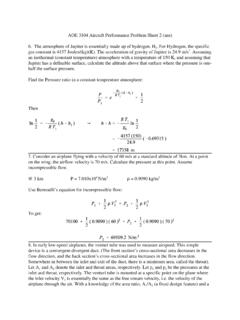
9 3 The pump shown here is used to lift a process liquid of density ft from a storage tank, and discharge it at a rate of cubic feet per second into the top of an absorber. The inlet to the absorber is located 25 feet above the free surface of the liquid in the storage tank, and the pump inlet is located at an elevation of 15 feet above that of the free surface. You can assume that the absorber operates at atmospheric pressure. A 2 ID pipe leads from the storage tank to the pump, while the pipe from the pump to the top of the absorber is of ID 3.
10 You can assume the losses in the 2 ID pipe to be 4 velocity heads, and the losses in the 3 ID pipe to be 5 velocity heads. Assuming the pump is 85% efficient, calculate the BHP (Brake Horse Power) of the pump. Example 1: Sizing a Pump1pump2 IDPipe3 ID Pipe2z25 ft15 ftstorage tankAbsorber5 ft 4 Solution First, we must identify locations 1 and 2 for applying the Engineering Bernoulli Equation . Recall that the pressure, velocity, and elevation at each of these locations appear in the Engineering Bernoulli Equation .