Transcription of Shell-and-Tube Heat Exchangers - Clarkson University
1 1 Shell-and-Tube heat Exchangers R. Shankar Subramanian Department of Chemical and Biomolecular Engineering Clarkson University Shell-and-Tube heat Exchangers are used widely in the chemical process industries, especially in refineries, because of the numerous advantages they offer over other types of heat Exchangers . A lot of information is available regarding their design and construction. The present notes are intended only to serve as a brief introduction. For detailed information about analyzing and designing Shell-and-Tube heat Exchangers , consult The Chemical Engineers Handbook ( ) (Chapter 11) or any of a variety of sources on heat exchanger design. Mechanical standards for Shell-and-Tube heat Exchangers are set by TEMA (Tubular Exchangers Manufacturers Association) and these supplement the ASME code for such heat Exchangers .
2 API (American Petroleum Institute) Standard 660 supplements both of these standards, and chemical and petroleum companies also have their own internal standards in addition. Advantages Here are the main advantages of Shell-and-Tube heat Exchangers (Thanks to Professor Ross Taylor for this list). 1. Condensation or boiling heat transfer can be accommodated in either the tubes or the shell , and the orientation can be horizontal or vertical. You may want to check out the orientation of the heat exchanger in our laboratory. Of course, single phases can be handled as well. 2. The pressures and pressure drops can be varied over a wide range. 3. Thermal stresses can be accommodated inexpensively. 4. There is substantial flexibility regarding materials of construction to accommodate corrosion and other concerns. The shell and the tubes can be made of different materials.
3 5. Extended heat transfer surfaces (fins) can be used to enhance heat transfer. 6. Cleaning and repair are relatively straightforward, because the equipment can be dismantled for this purpose. Basic considerations The tube side is used for the fluid that is more likely to foul the walls, or more corrosive, or for the fluid with the higher pressure (less costly). Cleaning of the inside of the tubes is easier than cleaning the outside. When a gas or vapor is used as a heat exchange fluid, it is typically 2 introduced on the shell side. Also, high viscosity liquids, for which the pressure drop for flow through the tubes might be prohibitively large, can be introduced on the shell side. The most common material of construction is carbon steel. Other materials such as stainless steel or copper are used when needed, and the choice is dictated by corrosion concerns as well as mechanical strength requirements.
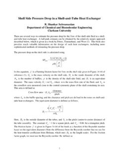
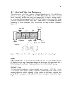
4 Expansion joints are used to accommodate differential thermal expansion of dissimilar materials. heat transfer aspects The starting point of any heat transfer calculation is the overall energy balance and the rate equation. Assuming only sensible heat is transferred, we can write the heat duty Q as follows. ()(),, ,, ,,hotp hothot inhot outcoldp coldcold outcold inQ mCTTm CTT= = lmQ UA F T= The various symbols in these equations have their usual meanings. The new symbol F stands for a correction factor that must be used with the log mean temperature difference for a countercurrent heat exchanger to accommodate the fact that the flow of the two streams here is more complicated than simple countercurrent or cocurrent flow. Consider the simplest possible Shell-and-Tube heat exchanger , called 1-1, which means that there is a single shell pass and a single tube pass.
5 The sketch schematically illustrates this concept in plan view. Note that the contact is not really countercurrent, because the shell fluid flows across the bank of tubes , and there are baffles on the shell side to assure that the fluid does not bypass the tube bank. The entire bundle of tubes (typically in the hundreds) is illustrated by a single line in the sketch. The baffle cuts are aligned vertically to permit dirt particles settling out of the shell side fluid to be washed away. 1T2T1t2tBaffle 3 The convention in Shell-and-Tube heat Exchangers is as follows: 1:T inlet temperature of the shell -side (or hot) fluid 2:T exit temperature of the shell -side (or hot) fluid 1:t inlet temperature of the tube-side (or cold) fluid 2:t exit temperature of the tube-side (or cold) fluid Thus, () ()12211221lnlmTt T tTTtTt = The fraction of the circular area that is open in a baffle is identified by a percentage cut and we refer to the types of baffles shown as segmented baffles.
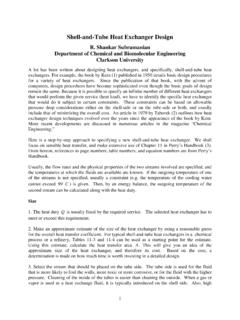
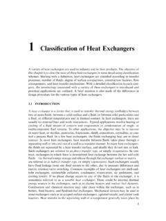
6 For the shell side, in evaluating the Reynolds number, we must find the cross-flow velocity across a bundle of tubes that occurs between a pair of baffles, and determine the value of this velocity where the space for the flow of the fluid is the smallest (maximum velocity). For the length scale, the tube outside diameter is employed. Most Shell-and-Tube heat Exchangers have multiple passes to enhance the heat transfer. Here is an example of a 1-2 (1 shell pass and 2 tube passes) heat exchanger . As you can see, in a 1-2 heat exchanger , the tube-side fluid flows the entire length of the shell , turns around and flows all the way back. It is possible to have more than two tube passes. Multiple shell passes also are possible, but involve fabrication that is more complex and is usually avoided, if possible. 1T2T1t2tBaffle 4 Correction factors to be used in the rate equation have been worked out by analysis, subject to a set of simplifying assumptions, for a variety of situations.
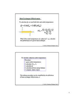
7 In the olden days, the formulae for them were considered too cumbersome to use. Therefore graphs were prepared plotting (),F PR, where 2111ttPTt = and 1221 TTRtt = are parameters on which F depends. Figures in Appendix C of the textbook by Mills display such graphs. Nowadays, one can compute these factors quickly with a pocket calculator. Given next are the two common factors. 2122211ln111ln1 RPRPRFARAR + = ++ + ()2242211ln21 11ln1 RPRPRFAB RAB R + = ++ + + + where ()()221,1 1 ARBPPRPP= = The first and second subscripts on the factor Fcorrespond to the number of shell and tube passes, respectively. The simplifying assumptions mentioned in the previous paragraph, given in Perry s Handbook, are as follows. 1. The heat exchanger is at steady state. 2. The specific heat of each stream remains constant throughout the exchanger .
8 3. The overall heat transfer coefficient U is constant. 4. All elements of a given fluid stream experience the same thermal history as they pass through the heat exchanger (see footnote in Perry for a discussion regarding the violation of this assumption in Shell-and-Tube heat Exchangers ). 5. heat losses are negligible. The formula given above for 12F also applies for one shell pass and 2, 4, (or any multiple of 2) tube passes. Likewise, the formula for 24F also applies for two shell passes and 4, 8, (or any multiple of 4) tube passes. In designing heat Exchangers , one should avoid the steep portion of the curves of Fversus P, because small errors in estimating P can cause large changes in the value of F. A misleading rule of thumb is that , but the correct idea is that the region of steep fall-off in the curves should be avoided.
9 5 heat Transfer Coefficients The evaluation of the overall heat transfer coefficient is an important part of the thermal design and analysis of a heat exchanger . You ll find several tables of typical overall heat transfer coefficients in Shell-and-Tube heat Exchangers in Chapter 11 of Perry s Handbook. The following generic result can be written for the overall heat transfer coefficient oU based on the outside surface area of the tubes , which is the heat transfer surface. ,0,111ooffioolmiiAArRRU h kAhA =++ ++ In the above equation, oh is the heat transfer coefficient for the fluid flowing in the shell , ih is the heat transfer coefficient for the fluid flowing through the tubes , iA and oA are the inside and outside surface areas of a tube, respectively, and lmA is their log mean. The fouling resistances on a unit area basis are,0fR for the shell side, and ,fiR for the tube side.
10 Accumulated information on fouling resistances can be found in the Standards published by TEMA. The inside heat transfer coefficient ih can be evaluated using the standard approach for predicting heat transfer in flow through tubes , including applying a viscosity correction where possible. Typically, turbulent flow can be expected, and a good design would aim to arrange for turbulent flow, because of the substantial enhancement in heat transfer provided by eddy transport. Predicting the shell -side heat transfer coefficient oh is more involved, because the flow passage is not simple, even in the absence of baffles. The presence of baffles needs to be taken into account in calculating the fluid velocity across the tube bank. heat transfer correlations for flow through tube banks are used, such as those given in the book by Holman (1).