Transcription of HEAT EXCHANGER
1 Unit Operations Lab heat EXCHANGER 1-1 heat EXCHANGER heat exchange is an important unit operation that contributes to efficiency and safety of many processes. In this project you will evaluate performance of three different types of heat exchangers (tubular, plate, and shell & tube). All these heat exchangers can be operated in both parallel- and counter-flow configurations. The heat exchange is performed between hot and cold water. Concepts to Review heat EXCHANGER configurations; parallel vs. counter-current flow LMTD and NTU methods for analysis of heat exchangers Convective and conductive heat transfer Reynolds, Prandtl, and Nusselt numbers Energy balance closure Degrees of Freedom and Performance Indicators The following degrees of freedom can be varied in this experiment: Flow rate and inlet temperature Th,i of hot water, Flow rate of cold water, heat EXCHANGER type (tubular, shell & tube, or plate), Flow direction (parallel or counter-flow).
2 You will investigate effects of these variables on the following performance indicators: Return temperatures Th,o and Tc,o of the hot and cold water heat flow rate q Overall heat transfer coefficient U Objectives Verify the overall energy balance. Investigate effects of the control parameters and the heat EXCHANGER configuration on the rate of the heat transfer, q, and the overall heat transfer coefficient, U. Investigate dependence of convective heat transfer coefficients on the Reynolds number and the flow geometry. To accomplish this goal, it is necessary to experimentally determine contributions of individual convective heat transfer coefficients to the overall heat transfer coefficient U.
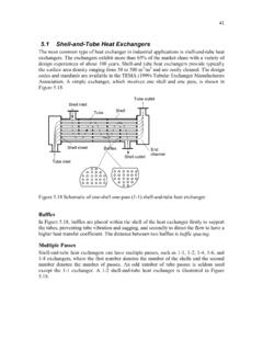
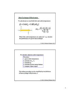
3 Check validity of the theoretical models, including boundary effects for flow that is not fully developed. Unit Operations Lab heat EXCHANGER 1-2 Theory Notes 1. The theory presented here is based on Ref. 1. Please refer to this book for more details. 2. Subscripts h and c refer to the hot and cold fluids, respectively, and subscripts i and o refer to the inlet and outlet of the heat EXCHANGER , respectively. , Th,i denotes temperature of the hot fluid at the inlet and Tc,o denotes temperature of the cold fluid at the outlet. Overall heat Transfer Coefficient U Consider energy balance in a differential segment of a single-pass heat EXCHANGER shown schematically in Fig.
4 1-1. The rate of heat transfer in this segment is ( ) = ( ) ( ), (1) where U is the overall heat transfer coefficient, T is the local temperature difference between the hot and cold fluids, and dA is the contact area in the differential segment. The overall heat transfer coefficient is inversely proportional to the total resistance Rtot to the heat flow. The latter is the sum of (1) resistance Rconv,h to convective heat transfer from the hot fluid to the partition between the fluids, (2) resistance Rp to thermal conduction through the partition, and (3) resistance Rconv,c to convective heat transfer from the partition to the cold fluid.
5 Therefore, =1 =1 , + + , . (2) Figure 1-1. Energy balance in a differential element of a single pass heat EXCHANGER operated in the counter-flow regime. Red, blue, and gray colors represent the hot fluid, cold fluid, and the partition between the fluids, respectively. The dashed rectangle shows a differential segment corresponding to the energy balance Eq. (1). Three resistances (Rconv,h, Rp, and Rconv,c) contributing to the total resistance to the heat transfer are indicated schematically. Unit Operations Lab heat EXCHANGER 1-3 Conductive heat transfer.
6 The resistance Rp to heat transfer through the partition depends on the system geometry. In the current experiment, you will need to consider heat conduction in the radial direction of a cylindrical tube and heat conduction across a thin plate. Resistances in both of these cases can be obtained analytically be solving the heat diffusion equation. Often, Rp can be neglected in comparison with Rconv,c and Rconv,h. If you choose to neglect Rp in analysis of your experiments, you should provide a justification for this approximation in your report.
7 Convective heat transfer. Resistance to the convective heat transfer is inversely proportional to the convective heat transfer coefficient, h = 1/Rconv. The convective heat transfer coefficient depends on fluid properties, flow geometry, and the flow rate. For example, the viscosity and flow rate of the fluid will have great effects on convective mixing within the fluid and, hence, resistance to heat transfer. These effects should be explored during this experiment. It is convenient to describe this dependence using several dimensionless numbers, namely the Reynold number = , (3) the Prandltl number = , (4) and the Nusselt number =.
8 (5) Here, , , k, and cp are the density, viscosity, thermal conductivity, and heat capacity of the fluid, v is the flow velocity, and Dh is the hydraulic diameter of the channel, =4 . Here, A is the cross-section area and P is the perimeter of the channel. In particular, the hydraulic diameter of for a circular pipe is equal to its diameter. Relationship between Re, Pr, and Nu depends on the system geometry and whether the flow is laminar and turbulent. For example, for a turbulent flow inside a circular pipe, = 1/3 (6) In your report you should provide all correlations relevant to the geometries and the flow regimes (turbulent and/or laminar) considered in this experiment.
9 Using Nu to find h for all flow conditions, the theoretical values for U can be obtained and compared with the values found experimentally. An error analysis for these two values should be included in the report. Since our experimental system allows us to determine directly only the overall heat transfer coefficient, it is necessary to design a strategy for extracting individual conductive heat transfer coefficients from your data. For example, in order to check the Nu-Re correlations for the Unit Operations Lab heat EXCHANGER 1-4 convective heat transfer in the cold water, we can vary the cold water flow rate while keeping all other system parameters constant.
10 Therefore, changes in the overall resistance Rtot observed in this set of experiments will be exclusively due to changes in the resistance , of the cold water convective transfer. This will allow us to determine how hconv,c depends on and, hence, how Nuc depends on Rec. A similar analysis can be performed for the convective transfer in hot water. Since the heat exchangers used in this lab are relatively small, it is not always accurate to assume that the flow in the EXCHANGER is fully developed. For this reason, thermal and velocity entry lengths must be taken into account.