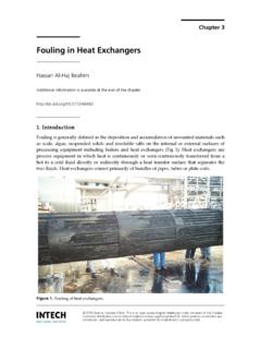
Transcription of Effectively Design Shell-and-Tube Heat Exchangers
1 Thermal Design of shell -and-tubeheat Exchangers (STHEs) isdone by sophisticated computersoftware. However, a good un-derstanding of the underlying principlesof exchanger Design is needed to use thissoftware article explains the basics of ex-changer thermal Design , covering suchtopics as: STHE components; classifica-tion of STHEs according to constructionand according to service; data needed forthermal Design ; tubeside Design ; shellsidedesign, including tube layout, baffling,and shellside pressure drop; and meantemperature difference. The basic equa-tions for tubeside and shellside heattransfer and pressure drop are well-known; here we focus on the applicationof these correlations for the optimum de-sign of heat Exchangers .
2 A followup arti-cle on advanced topics in shell -and-tubeheat exchanger Design , such as allocationof shellside and tubeside fluids, use ofmultiple shells, overdesign, and fouling,is scheduled to appear in the next of STHEsIt is essential for the designer to have agood working knowledge of the mechani-cal features of STHEs and how they in-fluence thermal Design . The principalcomponents of an STHE are: shell ; shell cover; tubes ; channel; channel cover; tubesheet; baffles; and components include tie-rods andspacers, pass partition plates, impinge-ment plate, longitudinal baffle, sealingstrips, supports, and foundation.
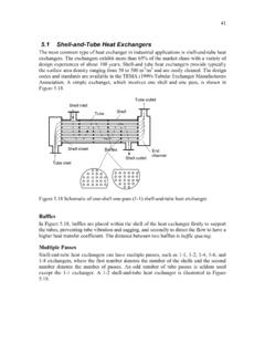
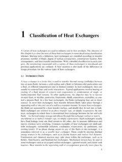
3 The Standards of the Tubular Ex-changer Manufacturers Association(TEMA) (1)describe these various com-ponents in STHE is divided into three parts:the front head, the shell , and the rearhead. Figure 1 illustrates the TEMA nomenclature for the various constructionpossibilities. Exchangers are described bythe letter codes for the three sections for example, a BFL exchanger has a bon-net cover, a two-pass shell with a longitu-dinal baffle, and a fixed-tubesheet based on constructionFixed fixed-tubesheetheat exchanger (Figure 2) has straighttubes that are secured at both ends totubesheets welded to the shell .
4 The con-struction may have removable channelcovers ( ,AEL), bonnet-type channelcovers ( ,BEM), or integral tubesheets( ,NEN). The principal advantage of the fixed-tubesheet construction is its low cost be-cause of its simple construction. In fact,the fixed tubesheet is the least expensiveconstruction type, as long as no expan-sion joint is required. Other advantages are that the tubes canbe cleaned mechanically after removal ofSHELL-AND-TUBE heat EXCHANGERSCHEMICAL ENGINEERING PROGRESS FEBRUARY 1998 Copyright 1997 American Institute of Chemical Engineers. All rights reserved.
5 Copying and downloading permitted with Design Shell-and-Tube heat ExchangersRajiv Mukherjee,Engineers India make the mostof exchanger Design software,one needs to understand STHE classification,exchanger components, tubelayout, baffling,pressure drop, andmean ENGINEERING PROGRESS FEBRUARY 1998 Shell-and-Tube heat EXCHANGERSn Figure 1. TEMA designations for Shell-and-Tube heat ShellTwo-Pass Shellwith Longitudinal BaffleSplit FlowDouble Split FlowDivided FlowCross FlowKettle-Type ReboilerABRemovable Channel and CoverCNBonnet (Integral Cover)Integral With TubesheetRemovable CoverDSpecial High-Pressure ClosuresTUWU-Tube BundlePull-Through Floating HeadFloating Head with Backing DeviceSPNO utside Packed Floating HeadFixed Tube SheetLike "C" Stationary HeadFixed Tube SheetLike "B" Stationary HeadExternally SealedFloating TubesheetFixed Tube SheetLike "A" Stationary Head Stationary Head TypesShell TypesRear Head TypesMLChannel Integral With Tubesheet and Removable Coverthe channel cover or bonnet.
6 And thatleakage of the shellside fluid is mini-mized since there are no flanged of this Design isthat since the bundle is fixed to theshell and cannot be removed, the out-sides of the tubes cannot be cleanedmechanically. Thus, its application islimited to clean services on the shell -side. However, if a satisfactory chem-ical cleaning program can be em-ployed, fixed-tubesheet constructionmay be selected for fouling serviceson the shellside. In the event of a large differentialtemperature between the tubes andthe shell , the tubesheets will be un-able to absorb the differential stress,thereby making it necessary to incor-porate an expansion joint.
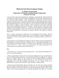
7 This takesaway the advantage of low cost to asignificant extent. the name implies, thetubes of a U-tube heat exchanger(Figure 3) are bent in the shape of aU. There is only one tubesheet in a U-tube heat exchanger. However, thelower cost for the single tubesheet isoffset by the additional costs incurredfor the bending of the tubes and thesomewhat larger shell diameter (dueto the minimum U-bend radius), mak-ing the cost of a U-tube heat ex-changer comparable to that of a fixed-tubesheet advantage of a U-tube heatexchanger is that because one end isfree, the bundle can expand or con-tract in response to stress differen-tials.
8 In addition, the outsides of thetubes can be cleaned, as the tube bun-dle can be disadvantage of the U-tubeconstruction is that the insides of thetubes cannot be cleaned Effectively ,since the U-bends would require flex-ible-end drill shafts for , U-tube heat Exchangers shouldnot be used for services with a dirtyfluid inside tubes . Floating floating-headheat exchanger is the most versatiletype of STHE, and also the this Design , one tubesheet is fixedrelative to the shell , and the other isfree to float within the shell . Thispermits free expansion of the tubebundle, as well as cleaning of boththe insides and outsides of the , floating-head SHTEs can beused for services where both theshellside and the tubeside fluids aredirty making this the standard con-struction type used in dirty services,such as in petroleum refineries.
9 There are various types of float-ing-head construction. The two mostcommon are the pull-through withbacking device (TEMAS) and pull-through (TEMAT) TEMAS Design (Figure 4) isthe most common configuration inthe chemical process industries (CPI).The floating-head cover is securedagainst the floating tubesheet by bolt-ing it to an ingenious split backingring. This floating-head closure is lo-cated beyond the end of the shell andcontained by a shell cover of a largerdiameter. To dismantle the heat ex-changer, the shell cover is removedfirst, then the split backing ring, andthen the floating-head cover, afterwhich the tube bundle can be re-moved from the stationary the TEMAT construction (Fig-ure 5), the entire tube bundle, includ-ing the floating-head assembly, canbe removed from the stationary end,since the shell diameter is larger thanthe floating-head flange.
10 The floating-head cover is bolted directly to thefloating tubesheet so that a split back-ing ring is not required. The advantage of this constructionis that the tube bundle may be re-moved from the shell without remov-ing either the shell or the floating-head cover, thus reducing mainte-nance time. This Design is particular-ly suited to kettle reboilers having adirty heating medium where U-tubescannot be employed. Due to the en-larged shell , this construction has thehighest cost of all exchanger 1998 CHEMICAL ENGINEERING PROGRESSS upportBracketStationaryTubesheetStationa ryTubesheetBonnet(StationaryHead)Bonnet( StationaryHead)BafflesTie Rodsand Spacersn Figure 2.