Transcription of Engineering Reference Guide - Compumotor
1 B223 Parker Hannifin CorporationCompumotor DivisionRohnert Park, CaliforniaCatalog 8000-3/USAC ompumotor CatalogEngineering ReferenceTo access additional product information, please visit us on the web at ReferenceGuideOver the past twenty years, Compumotor has beendeveloping an Engineering Reference thatcompiles important information on the technol-ogy and practical application of motioncontrol. Compumotor s EngineeringReference was the foundation for theVirtual Classroom CD ROM. The VirtualClassroom CD-ROM is an interactive,multi-media tool that makes theEngineering Reference come request your free copy, go your convenience, we areproviding an abbreviated versionof the Engineering Referencethat concentrates on the Sizingand Selection of a motionsystem.
2 In the future, thecomplete Engineering Referencewill be printed as a separate textto allow greater use and distribu-tion to colleges and the website for ReferenceTable of Contents: Sizing and Selection Process223 Sizing and Selection Software232 Application Considerations233 Technology Comparison Summary235 Glossary of Terms237 Technical Data240 Advanced Application Examples241 6000 Position-Based Following241 Contouring (Circular Interpolation)245 motor Sizing and Selection ProcessBefore you can select your motors drives and controls, youmust define the mechanical system and determine theperformance requirements of each axis of motion.
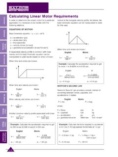
3 Theinformation in this section will help you:1. Calculate move profile for each axis of Calculate total inertia for each axis of motion3. Calculate torque required for acceleration for each axis ofmotion4. Calculate max motor speed for each axis of motion5. Review the application considerations to determine special224 Parker Hannifin CorporationCompumotor DivisionRohnert Park, CaliforniaCatalog 8000-3/USAC ompumotor CatalogEngineering ReferenceSizing & Selection ProcessExampleYou need to move 6" in 2 secondsa = -d == == Step 1: Move ProfileBefore calculating torque requirements of an application, youneed to know the velocities and accelerations needed.
4 Forthose positioning applications where only a distance (X) and atime (S) to move that distance are known, the trapezoidalmotion profile and formulas given below are a good startingpoint for determining your requirements. If velocity and accel-eration parameters are already known, you can proceed to oneof the specific application examples on the following distance X in time that:1. Distance X/4 is moved in time S/3 (Acceleration)2. Distance X/2 is moved in time S/3 (Run)3. Distance X/4 is moved in time S/3 (Deceleration)The graph would appear as follows:The acceleration (a), velocity (v) and deceleration (d) may becalculated in terms of the knowns, X and = at =x=a = -d ====S/32S/3SS/3S/3S/30 VadVelocitytimeDistance: _____ Inches of Travel _____ revolutions of motorMove Time: _____ secondsAccuracy: _____ arcminutes, degrees or inchesRepeatability: _____ arcseconds, degrees or inchesDuty Cycleon tme: _____ secondsoff time: _____ secondsCycle Rate: _____ sec.
5 Min. hour2Xt2X( 4 )2X2 x 9S2S( 3 ) (6 inches)(2 seconds) (6 inches)(2 seconds)2inchessecond2 Sizing Step 2 and Step 3: Inertia and Torque Application DataInertia of Leadscrews per Move Profile ConsiderationsLeadscrew DrivesLeadscrews convert rotary motion to linear motion and come ina wide variety of configurations. Screws are available withdifferent lengths, diameters, and thread pitches. Nuts rangefrom the simple plastic variety to precision ground versions withrecirculating ball bearings that can achieve very high combination of microstepping and a quality leadscrewprovides exceptional positioning resolution for many applica-tions.
6 A typical 10-pitch (10 threads per inch) screw attached toa 25,000 step/rev. motor provides a linear resolution " (4 millionths, or approximately micron) per flexible coupling should be used between the leadscrew andthe motor to provide some damping. The coupling will alsoprevent excessive motor bearing loading due to Hannifin CorporationCompumotor DivisionRohnert Park, CaliforniaCatalog 8000-3/USAC ompumotor CatalogEngineering ReferenceTo access additional product information, please visit us on the web at & Selection ProcessLeadscrew EfficienciesEfficiency (%)
7 TypeHighMedianLowBall-nut959085 Acme with metal nut*554035 Acme with plastic nut856550*Since metallic nuts usually require a viscous lubricant, thecoefficient of friction is both speed and of Static Friction Materials(Dry Contact Unless Noted) SSteel on on Steel (lubricated) on on on on Steel FormulasThe torque required to drive load W using a leadscrew withpitch (p) and efficiency (e) has the following components:TTotal = TFriction + TAccelerationTFriction =Where:F = frictional force in ouncesp = pitch in revs/ine = leadscrew efficiencyF = s W for horizontal surfaces where s = coefficient of staticfriction and W is the weight of the load.
8 This friction componentis often called breakaway .Dynamic Friction: F = DW is the coefficient to use for frictionduring a move profile. However, torque calculations foracceleration should use the worst case friction coefficient, =(JLoad + JLeadscrew + JMotor) = 2 pvJLoad =; JLeadscrew =Where:T = torque, oz-in = angular velocity, radians/sect = time, secondsv = linear velocity, in/secL = length, inchesR = radius, inchesF2 pe1g tw(2 p)2 L R42 Leadscrew DrivesVertical or Horizontal Application:STScrew type, ball or acmeST =eEfficiency of screwe =% SFriction coefficient S =LLength ofscrewL =inchesDDiameter of screwD =inchespPitchp =threads/inchWWeight of loadW = forceF =ouncesDirectly coupled to the motor ?
9 Yes/noIf yes, CT Coupling typeIf no, belt & pulley or gearsRadius of pulley or gearinchesGear: Number of teeth Gear 1 Number of teeth Gear 2 Weight of pulley or gearouncesWeight of beltounces = density, ounces/in3g = gravity constant, 386 in/sec2 The formula for load inertia converts linear inertia into therotational equivalent as reflected to the motor shaft by the torque required to accelerate a 200-lb steel loadsliding on a steel table to 2 inches per second in 100 millisec-onds using a 5 thread/inch steel leadscrew 36 inches long inches in diameter.
10 Assume that the leadscrew has anAcme thread and uses a plastic nut. motor inertia is given oz-in2. In this example, we assume a horizontally orientedleadscrew where the force of gravity is perpendicular to thedirection of motion. In non-horizontal orientations, leadscrewswill transmit varying degrees of influence from gravity to themotor, depending on the angle of inclination. CompumotorSizing Software automatically calculates these torques usingvector Calculate the torque required to overcome friction. Thecoefficient of static friction for steel-to-steel lubricantcontact is The median value of efficiency for an Acmethread and plastic nut is Therefore.