Transcription of English Lutron Technical Support Center …
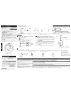
1 Lutron Electronics Co., Suter RoadCoopersburg, PA 18036-1299, 0301683 Rev. A 05/2013 EnglishSingle-Pole:Insulated wires connected to two screws of the same color. See Step 5a when :Insulated wires connected to three screws. One of these wires is connected to a screw of a different color (not green) or labeled COMMON. MARK or TAG this wire to identify it when wiring. See Step 5b when screw (Common). Actual location may (Bare Copper or Green Wire)Ground (Bare Copper or Green Wire)Installation1 Turn OFF Power. Turn power OFF at circuit break er or remove Wallplate and Switch. Remove wallplate and switch mounting screws. Carefully remove switch from wall (do not remove wires).WARNING: Shock Hazard. May result in serious injury or death. Turn off power at circuit breaker before installing the the Type of Switch Technical Support Center 24 hrs / 7 days Note: Your wall switch may have two wires attached to the same screw (see illustrations below for examples).
2 Tape these two wires together before disconnecting. Connect both wires to the control wire in Step wire in the backwired hole and one to the Wire:Turn screw to Terminals: Turn screws to Terminals:Insert screwdriver. Pull wire installations involving more than one control in wallbox, refer to Multi-Unit Installations before V~ 60 Hz AModels:DVFSQ-F-HODVSCFSQ-F-HOLXFSQ-F-HO 120 V~ 60 Hz 2 AModels: Technical AssistanceIf you have questions concerning the installation or operation of this product, call the Lutron Technical Support Center . Please provide exact model number when and Canada (24 hrs/7days) + Other countries 8am 8pm ET+ + Warranty (Valid only in , Canada, Puerto Rico, and the Caribbean.) Lutron will, at its option, repair or replace any unit that is defective in materials or manufacture within one year after purchase.
3 For warranty service, return unit to place of purchase or mail to Lutron at 7200 Suter Rd., Coopersburg, PA 18036-1299, postage WARRANTY IS IN LIEU OF ALL OTHER EXPRESS WARRANTIES, AND THE IMPLIED WARRANTY OF MERCHANTABILITY IS LIMITED TO ONE YEAR FROM PURCHASE. THIS WARRANTY DOES NOT COVER THE COST OF INSTALLATION, REMOVAL OR REINSTALLATION, OR DAMAGE RESULTING FROM MISUSE, ABUSE, OR DAMAGE FROM IMPROPER WIRING OR INSTALLATION. THIS WARRANTY DOES NOT COVER INCIDENTAL OR CONSEQUENTIAL DAMAGES. Lutron S LIABILITY ON ANY CLAIM FOR DAMAGES ARISING OUT OF OR IN CON NEC TION WITH THE MANUFACTURE, SALE, INSTALLATION, DELIVERY, OR USE OF THE UNIT SHALL NEVER EXCEED THE PUR CHASE PRICE OF THE UNIT. This warranty gives you specific legal rights, and you may have other rights which vary from state to state.
4 Some states do not allow the exclusion or limitation of incidental or consequential damages, or limitation on how long an implied warranty may last, so the above limitations may not apply to Claro and Fassada are registered trademarks of Lutron Electronics Co., Inc. NEC is a registered trademark of National Fire Protection Association, Quincy, Massachusetts. 2013 Lutron Electronics Co., Off Side SectionsEach Control Has Inside Sections RemovedMiddle Control Has Two Side Sections RemovedImportant Notes: Please read before CAUTION: To avoid overheating and possible damage to other equipment, do not use to control receptacles, lighting, fluorescent lighting fixtures, or transformer-supplied Do not use control with a fan and light that operate with the same When no grounding means exists within the wallbox for an existing control, the 2011 National Electrical Code (NEC ) allows a control to be installed as a replacement as long as 1) a nonmetallic, noncombustible faceplate is used with nonmetallic attachment screws or 2) the circuit is protected by a ground fault circuit interrupter.
5 The 2008 NEC has the same allowances but does not contain the requirement for nonmetallic attachment screws. When installing a control according to any of these methods, cap or remove the green wire before screwing the control into the Wiring controls in a circuit which contains a ground fault circuit interrupter (GFCI) or an arc fault circuit interrupter (AFCI) may cause nuisance tripping and is not Use control with a ceiling paddle fan only. Use only one ceiling paddle fan per For new installations, wire a test switch before installing the Set multi-speed fans to their highest setting before installing Use only one control in a 3-way Install in accordance with all national and local electrical Clean control with a soft damp cloth only. Do not use any chemical InstallationsWhen combining controls in one wallbox, remove all inner side sections before wiring (see at right).
6 Use pliers to bend each side section up and down until it breaks off. Reduction of control capacity is not Pole/3-WayQuiet Fan-Speed Controls7 Turn ON Power. Turn ON power at circuit break er or replace Control to Wallbox. Form wires carefully into the wallbox, mount and align control. Install faceplate. Note: Only one control can be used in a 3-way circuit. Control can be used in either location. Connect the green ground wire on the control to the bare copper or green ground wire in the wallbox. (See Important Note 3.) Connect black control wire to the tagged wire removed from the switch. If you had taped together two wires (see step 4), connect both wires to the black control wire screw and remove the tape Connect the red wire on the control to one of the remaining wires removed from the switch. Connect the red/white wire on the control to the remaining wire removed from the switch.
7 Connect the green ground wire on the control to the bare copper or green ground wire in the wallbox. (See Important Note 3.) Connect the black control wire to one of the wires removed from the switch. If you had taped together two wires (see step 4), connect both wires to the black control wire and remove the tape. Connect the red wire on the control to the other wire removed from the switch. Cap off the red/white wire on the control. Do NOT connect to any other wire or 5a - Single-Pole Wiring 5b - 3-Way WiringORGreenGroundRedRed / WhiteBlackGroundRedRed / WhiteBlackTag120 V~60 HzLive BlackRedRed/WhiteGreenGroundNeutralFanCo ntrolRedRed/WhiteGreenGroundGroundFanNeu tral3-WaySwitchControlNote: Depending on model number, the control may include a Lutron Claro or Fassada wallplate. A Lutron wallplate consists of 2 parts, a faceplate (front) that snaps into an adapter plate (back).
8 Please detach faceplate from adapter plate before installing. This will expose control mounting holes and prevent faceplate damage during top of faceplate and pull forward to detach it from adapter (Front)Adapter plate (Back) Note: Control can be installed in either standard ClaroR or FassadaR wallplate which consists of 2 parts, an adapter plate (back) and faceplate (front).ORFaceplate (Front)Adapter plate (Back)Note: Do not overtighten mounting screws. Permanent damage may on faceplateNote: Follow recommended strip lengths and combinations for supplied wire connectors. Wire connectors are suitable for copper wire only. For aluminum wire, consult an wire connector that no bare wire is the Control. For installations involving more than one control in a wallbox, refer to the section on Multi-Unit Installations before V~60 HzLive BlackGreen03016830301683 Easy-to-follow Instructions Instrucciones f ciles de seguir Instructions faciles suivre Easy-to-follow Instructions Instrucciones f ciles de seguir Instructions faciles suivre 03016830301683 Easy-to-follow Instructions Instrucciones f ciles de seguir Instructions faciles suivre Easy-to-follow Instructions Instrucciones f ciles de seguir Instructions faciles suivre Do Not Remove Outside SectionsRemarques importantes : Veuillez lire attentivement avant de proc der l' ATTENTION.
9 Afin d' viter une surchauffe et des dommages ventuels d'autres quipements, veuillez ne pas utiliser pour le contr le des prises de courant, de l' clairage, des appareils d' clairage fluorescents, ou des appareils aliment s par un N'utilisez pas la commande avec les ventilateurs et la lumi re qui op rent avec le m me Si aucun dispositif de mise la terre n'existe dans le bo tier mural d'une commande existante, le 2011 National Electrical Code (NEC , code lectrique national) autorise l'installation d'une commande en guise de remplacement condition 1) qu'une plaque frontale non-m tallique et non-combustible soit utilis e avec des vis de fixation non-m talliques, ou 2) que le circuit soit prot g par un disjoncteur de fuite de terre. Le code NEC 2008 comprend les m mes directives l'exception de l'exigence concernant les vis de fixation non-m talliques.
10 Lors de l'installation d'une commande selon l'une de ces m thodes, couvrez le fil vert d'un capuchon ou retirez-le avant de visser le commande dans le bo tier C bler les commandes dans un circuit qui contient un interrupteur diff rentiel (GFCI) ou un d tecteur d'arc lectrique (AFCI) pourra provoquer de l g res nuisances et n'est pas recommand .5. Utilisez la commande seulement avec un ventilateur de plafond. N'utilisez qu'un seul ventilateur de plafond par Pour de nouvelles installations, c blez un interrupteur de test avant d'installer la commande. 7. R glez les ventilateurs plusieurs vitesses sur leurs plus hauts param tres avant d'installer les contr N'utilisez qu'une seule commande dans un circuit Installez le dispositif en accord avec tous les codes lectriques locaux et Nettoyez la commande seulement avec un chiffon doux humide.