Transcription of Enhanced isoCink+TM Bridge Rectifiers
1 PB5006, PB5008, General Semiconductor Revision: 30-Jul-20181 Document Number: 84809 For technical questions within your region: DOCUMENT IS SUBJECT TO CHANGE WITHOUT NOTICE. THE PRODUCTS DESCRIBED HEREIN AND THIS DOCUMENTARE SUBJECT TO SPECIFIC DISCLAIMERS, SET FORTH AT isoCink+TM Bridge Rectifiers *Tested to UL standard for safety electrically isolated semiconductor devices. UL 1557 4th edition. Dielectric tested to maximum case, storage and junction temperature to 150 C to withstand 1500 V.
2 Epoxy meets UL 94 V-0 flammability UL recognition file number E312394 (QQQX2) UL 1557 (see *) Enhanced high-current density single in-line package Superior thermal conductivity Glass passivated chip junction Solder dip 275 C max. 10 s, per JESD 22-B106 Material categorization: for definitions of compliance please see APPLICATIONSG eneral purpose use in AC/DC Bridge full wave rectification for switching power supply, home appliances and white-goods DATACase: PB Molding compound meets UL 94 V-0 flammability rating Base P/N-E3 - RoHS-compliant, commercial gradeTerminals.
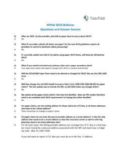
3 Matte tin plated leads, solderable per J-STD-002 and JESD 22-B102 E3 suffix meets JESD 201 class 1A whisker testPolarity: As marked on bodyMounting Torque: 10 cm-kg ( inches-lbs) Torque: cm-kg (5 inches-lbs) Notes(1)With heatsink(2)Without heatsink, free airPRIMARY CHARACTERISTICSP ackagePBIF(AV)45 AVRRM600 V, 800 V, 1000 VIFSM450 AIR10 AVF at IF = VTJ CCircuit configurationIn-line+~~--~~+~~isoCink+ Case Style PB+~ ~ -MAXIMUM RATINGS (TA = 25 C unless otherwise noted)PARAMETERSYMBOL PB5006PB5008PB5010 UNIT Maximum repetitive peak reverse voltage VRRM 6008001000V Average rectified forward current (Fig.)
4 1, 2)TC = 84 C (1)IO45A TA = 25 C (2) peak forward surge current ms single sine-wave, TJ = 25 CIFSM 450A Rating for fusing (t < ms) TJ = 25 CI2t840A2sOperating junction and storage temperature range TJ, TSTG -55 to +150 C PB5006, PB5008, General Semiconductor Revision: 30-Jul-20182 Document Number: 84809 For technical questions within your region: DOCUMENT IS SUBJECT TO CHANGE WITHOUT NOTICE. THE PRODUCTS DESCRIBED HEREIN AND THIS DOCUMENTARE SUBJECT TO SPECIFIC DISCLAIMERS, SET FORTH AT (1)Pulse test: 300 s pulse width, 1 % duty cycle(2)Pulse test.
5 10 ms pulse widthNotes(1)With 60 W air cooled heatsink(2)Without heatsink, free airELECTRICAL CHARACTERISTICS (TA = 25 C unless otherwise noted)PARAMETERTEST CONDITIONSSYMBOL Maximum instantaneous forward voltage per diode (1)IF = A TA = 25 C VF TA = 125 C current per diode (2)rated VRTA = 25 C IR -10 A TA = 125 C 170500 Typical junction capacitance per V, 1 MHzCJ 162-pFTHERMAL CHARACTERISTICS (TA = 25 C unless otherwise noted)PARAMETERSYMBOL PB5006PB5008PB5010 UNIT Typical thermal resistanceR JC (1) C/W R JA (2)18 ORDERING INFORMATION (Example)PREFERRED P/NUNIT WEIGHT (g)PREFERRED PACKAGE CODEBASE QUANTITYDELIVERY MODEPB5006-E3 , PB5008, General Semiconductor Revision: 30-Jul-20183 Document Number: 84809 For technical questions within your region: DOCUMENT IS SUBJECT TO CHANGE WITHOUT NOTICE.
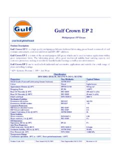
6 THE PRODUCTS DESCRIBED HEREIN AND THIS DOCUMENTARE SUBJECT TO SPECIFIC DISCLAIMERS, SET FORTH AT AND CHARACTERISTICS CURVES (TA = 25 C unless otherwise noted)Fig. 1 - Derating Curve Output Rectified CurrentFig. 2 - Forward Current Derating CurveFig. 3 - Forward Power DissipationFig. 4 - Typical Forward Characteristics Per DiodeFig. 5 - Typical Reverse Characteristics Per DiodeFig. 6 - Typical Junction Capacitance Per Diode040801600515202550 Case Temperature ( C)Average Forward Output Current (A)102060120 With HeatsinkSine-Wave, R-Load10014030454035 TCTCTC Measured at Device Bottom01235 Ambient Temperature ( C)Average Forward Rectified Current (A)05025751001251504 Without HeatsinkSine-Wave, R-LoadFree Air, TA051015202555040 Average Forward Current (A)Forward Power Dissipation (W) Forward Voltage (V)Instantaneous Forward Current (A)
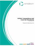
7 TA = 150 CTA = 125 CTA = 25 = 100 CTA = 85 of Rated Peak Reverse Voltage (%) Instantaneous Reverse Current ( A) TA = 150 CTA = 125 CTA = 25 = 100 CTA = 85 Voltage (V)Junction Capacitance (pF)100TJ = 25 Cf = MHzVsig = 50 mVp-pPB5006, PB5008, General Semiconductor Revision: 30-Jul-20184 Document Number: 84809 For technical questions within your region: DOCUMENT IS SUBJECT TO CHANGE WITHOUT NOTICE. THE PRODUCTS DESCRIBED HEREIN AND THIS DOCUMENTARE SUBJECT TO SPECIFIC DISCLAIMERS, SET FORTH AT OUTLINE DIMENSIONS in inches (millimeters)Case Type ( ) ( ) ( ) ( ) ( ) ( ) ( ) ( ) ( ) ( ) ( ) ( ) ( ) ( ) ( ) ( ) ( ) ( )5 Side ViewSide ViewFront Side ( ) ( ) ( ) ( ) ( ) ( ) ( ) ( ) ( ) ( ) ( ) ( ) ( ) ( ) ( ) ( ) ( ) ( ) ( ) ( ) ( ) ( ) ( ) ( ) ( ) x 45 CHAMFERL egal Disclaimer Revision: 08-Feb-171 Document Number.
8 91000 Disclaimer ALL PRODUCT, PRODUCT SPECIFICATIONS AND DATA ARE SUBJECT TO CHANGE WITHOUT NOTICE TO IMPROVE RELIABILITY, FUNCTION OR DESIGN OR OTHERWISE. vishay Intertechnology, Inc., its affiliates, agents, and employees, and all persons acting on its or their behalf (collectively, vishay ), disclaim any and all liability for any errors, inaccuracies or incompleteness contained in any datasheet or in any other disclosure relating to any makes no warranty, representation or guarantee regarding the suitability of the products for any particular purpose or the continuing production of any product.
9 To the maximum extent permitted by applicable law, vishay disclaims (i) any and all liability arising out of the application or use of any product, (ii) any and all liability, including without limitation special, consequential or incidental damages, and (iii) any and all implied warranties, including warranties of fitness for particular purpose, non-infringement and merchantability. Statements regarding the suitability of products for certain types of applications are based on vishay s knowledge of typical requirements that are often placed on vishay products in generic applications.
10 Such statements are not binding statements about the suitability of products for a particular application. It is the customer s responsibility to validate that a particular product with the properties described in the product specification is suitable for use in a particular application. Parameters provided in datasheets and / or specifications may vary in different applications and performance may vary over time. All operating parameters, including typical parameters, must be validated for each customer application by the customer s technical experts.