Transcription of Ep1 - Sparling Instruments
1 TM Original Issue Date: March 2002 Revision 160323 FM657 FM656 FM626 Sanitary FM626 FM627 TABLE O F CONTENTS Page SECTION 1 - GENERAL .. 1 Measuring System .. 1 Operating Principal .. 1 Application to Magnetic Flow Measurement .. 1 Interference .. 2 System Operation .. 3 Construction .. 4 Specifications .. 5 Interchangeability .. 7 Flow Rates, Dimensions & Weight .. 7 SECTION 2 - PRE-INSTALLATION .. 10 Receiving and Inspection .. 10 Storage .. 10 Return of Equipment .. 10 SECTION 3 - INSTALLATION .. 11 Application Considerations .. 11 Site Selection .. 11 Rotating the Transmitter Display.
2 12 Removable Electrodes .. 13 Hot-Tap Removable Electrodes .. 13 Pipe Connections .. 15 Special Mounting Bolts & Gaskets .. 16 Grounding .. 20 Electrical Connections .. 21 Remote Mounted Transmitter .. 24 Lightening Protection .. 28 SECTION 4 - START-UP .. 28 Start-Up Procedure .. 28 SECTION 5 - CALIBRATION .. 28 Calibration .. 28 SECTION 6 - MAINTENANCE .. 29 SECTION 7 - TROUBLESHOOTING .. 29 General .. 29 Troubleshooting Chart .. 29 Electronics Self Test .. 31 Electronics Module Replacement .. 31 Sensor Testing .. 32 Coil Continuity Testing.
3 33 Coil Insulation Test .. 33 Page Electrode Circuit Insulation Test .. 33 SECTION 8 REPLACEMENT PARTS LIST .. 34 APPENDIX 1- PROGRAMMING .. 35 General .. 35 Entering Data .. 35 Batching Modes .. 36 Show Meter Data .. 36 Password Entry .. 36 Rescale Rate .. 37 Select Rate Units .. 37 Set Full Scale .. 38 Select Rate as % of Full Scale .. 38 Rescale Total .. 38 Lockout .. 38 Alarms .. 39 Count Direction .. 39 Select Total Units .. 39 Set Registration .. 40 Reset Totalizer .. 40 Set Outputs .. 40 Select Pulse Width.
4 40 Backlight .. 41 Set Flow Direction .. 41 Empty Pipe Detection .. 41 Protocol .. 41 Damping Adjustments .. 42 Display Damping .. 42 Current Damping .. 42 Low Flow Cutoff .. 42 Exit Programming .. 42 Change Password .. 42 Change Tag .. 43 Diagnostics .. 43 Check HART Transmission .. 43 Check Coil Current .. 43 Check Current Loop .. 44 Calibrate 4- 20mA Loop .. 44 Set Frequency .. 44 Simulate 75% FS .. 45 Simulator Check .. 45 IDS-626/627/656/657 Page i TABLE O F CONTENTS cont'd. APPENDI X 2 Batch Programming Page Page and Operation.
5 46 General .. 46 Programming .. 46 Lockout .. 46 Rescale Total .. 47 Batch On/Off .. 47 Alarms .. 47 Count Direction .. 47 Select Total Units .. 48 User Defined Totalizer Units .. 48 Conversion Factor .. 48 Description of Operating .. 49 APPENDIX 3 - Communication .. 50 RS232 Sparling Protocol .. 50 RS485 .. 51 FIGURES Measuring Principal .. 1 Block Diagram .. 3 Dimensions .. 8 Full Pipe Required .. 11 Changing th e Rotatable Display .. 12 Hot Tap Electrode .. 13 Removing the Electrode .. 14 FM626 Gasket Installation.
6 18 FM626 Sensor Position .. 18 FM656 Gasket Installation .. 19 FM656 Sensor Position .. 19 Grounding .. 20 Conduit Connections .. 21 Electrical Connections I/O PCB .. 22 Installing Diode Across Inductive Loads .. 23 TigermagEP Remote Display .. 24 FIGURES cont'd. TigermagEP Remote Conduit Connections .. 24 TigermagEP Standard Motherboard .. 25 Remote Mounted Transmitter .. 27 Power Supply Voltage Ratings .. 28 Access to Electronics .. 31 Removing the Electronics Module .. 31 Aligning Electronics Module with Card Guides .. 32 Replacing the E2 PROM Chip.
7 32 Coil Resistance Testing .. 33 Coil Insulation Testing .. 33 Electrode Circuit Insulation Test .. 33 TigermagEP Display .. 35 Main Program .. 36 Rescale Rate Flow Chart .. 37 Rescale Total Flow Chart .. 38 Set Outputs Flow Chart .. 40 Connecting HART Communicator .. 41 Set Damping Flow Chart .. 42 Change Tag .. 43 Diagnostics Flow Chart .. 43 Simulate Mode .. 45 Enclosure fo r TigermagEP with Batching .. 46 Rescale Rate w/Batcher Flowchart .. 47 TABLES Flow Rates .. 7 .. 7 .. 9 Material.
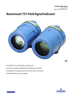
8 15 .. 16 , Flange & BoltSpecifications .. 17 Page ii TigermagEP Modbus RTU ..52 General Measuring System The Sparling TigermagEPTM Model FM-626, FM627, FM-656 and FM-657 flowmeters are obstructionless devices fo r monitoring th e volumetric flo w of conductive liquids in ful l closed pipes. The flowmeter consists of a sensor (wafer or flanged) with a nonmagnetic liner, sensing electrodes and a measuring transmitter. Operation is based on Faraday s Law of Mag- netic Induction. An electrically conductive liquid flowing through a magnetic field induces a volt- Operating Principle age which is perpendicular to this field and to the direction of the flow.
9 This voltage is proportional to the average flow velocity. See Figure The mathematical formula describing Faraday s law reads: E = B x L x V E = Induced voltage B = Magnetic field intensity (flux density) L = Distance between the electrodes (pipe diameter) V = Average flow velocity of liquid Application to Magnetic Flow Measurement Measuring Principle Figure In a magnetic flowmeter th e liquid acts as a moving conductor as it flows through th e pipe. The induced voltage (E) in the liquid is measured by two sensing electrodes mounted opposite each other in the meter sensing head.
10 The length of th e conductor is equal to the distance between sensing electrodes and also the internal diameter (D) of the pipe. The flux density is proportional to the coil current (I) , times a constant (k). The above formula can be restated as follows: E = I x k x D x V flow 0 V = cross sectional area = A 0 x I x 4 x k E = D2 Note that if I is held constant, E is proportional to 0 or the induced voltage is directly proportional to the average flow rate (V). IDS-626/627/656/657 Page 1 Interference Electrochemical Interference The signal voltage is measured by two electrodes.