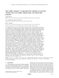
Transcription of Equivalent roughness for pressure drop calculations in ...
1 13th United States/North American Mine Ventilation Symposium, 2010 Hardcastle & McKinnon (Eds.) Equivalent roughness for pressure drop calculations in mine ventilation C. Montecinos SKM Chile, Santiago, Chile K. Wallace, Jr. Mine Ventilation Services, Inc., Clovis, California, USA ABSTRACT: The generalized procedure for the calculation of the pressure drop along tunnels is by using Atkinson s equation. The friction factor in Atkinson s equation is determined from measured or computed values of airway dimensions and tunnel interior finishing according to mining method and ground support type. This paper re-visits the friction factor according to Colebrook s relationship and the darcy -Weisbach equation, which are widely used in mechanical engineering.
2 This method of calculating the friction has the advantage of a more reliable determination since the size of the airway is implicit in the method and only a representative absolute roughness has to be selected to determine the friction factor. Measurements of pressure drop performed at Codelco s El Teniente mine, Chile, permitted the determination of the absolute roughness for different tunnel sizes and wall finishing. 1 Introduction In the technical literature for mine ventilation, the generalized procedure for the calculation of the pressure drop along tunnels is to derive the airway s resistance by using Atkinson s equation. This resistance is determined from measured or computed values of airway dimensions and the tunnel s interior finishing, including the type of ground support and mining method.
3 Of all the factors in Atkinson s equation, the friction factor can be the most challenging to estimate. It has been documented (Blevins 1984) that friction factor can be related to fluid dynamic properties and the roughness of the tunnel walls to the diameter of the tunnel. This paper re-visits the friction factor according to Colebrook s relationship and the darcy -Weisbach equation, which are widely used in mechanical engineering, and by correlating the roughness with actual data measured for different tunnel sizes and wall finishing. This method of calculating friction factor has the advantage of a more reliable determination of the friction since the size of the airway is implicit in the method.
4 An example problem is presented to show the impact of airway size on the calculation of friction factor. 2 Theoretical background In modern fluid mechanics, the friction factor used to determine the pressure drop of a fluid flowing through ducts or airways is defined by a function of dimensionless parameters which characterizes it for different fluid properties, the size of the duct and the roughness of the inside surface. The calculation of the pressure drop of the air flow according to the darcy -Weisbach Equation (1) is defined as follows: 2v2maihttiDLfKp += (1) where p = pressure drop (Pa) iK = Losses in tunnel hD = Hydraulic diameter (m) tf = friction factor (dimensionless) mv = Air velocity (m/s) tL = Length of tunnel (m) a = Air Density (kg/m3) If consistent units are used then the result is defined by the velocity head2v2ma (Pa).
5 The air velocity corresponds to the mean airflow divided by the cross sectional area and is obtained from Equation (2). tAQ=mv (2) where Q = Average airflow (m3/s) tA = Tunnel area (m2). The hydraulic diameter is a characteristic dimension representative of the tunnel and depends of the area and 225 2010, MIRARCO - Mining Innovation perimeter and is shown in Equation (3). The use of it simplifies the analysis and gives good results for typical cross sections of mine tunnels and shafts. tthPAD4= (3) where tP = wetted perimeter of Tunnel area (m). However, for more accurate analyses, an improved Equivalent diameter calculation should be used for turbulent flow (Blevins, 1984).
6 This is not an Equivalent diameter of a circular section from which the area could be calculated; rather the area must be obtained from the geometry of the tunnel section. The wetted perimeter of Equation (3) in this case generally corresponds to the contour of the tunnel section since the air floods all the area and is a parameter which characterizes the wall friction . The singular loss factors iK of Equation (1) corresponds to a multiplier of the velocity head to account for the pressure drop of tunnel curves, inlets, exhaust, splits, joints, section transitions, etc. and are obtained from tables (for example see the work of Blevins (1984)). In Equation (1) each loss within the same tunnel section must have the same area.
7 If transitions, or shock losses, occur in the tunnel, then the pressure drop through the tunnel must be divided into more sections in order to compute the various transition losses and ensure that each section s velocity head is accounted for in each calculation . To obtain the friction factor, the Reynolds number, Re, and the relative roughness , t , must be calculated according to Equations (4) & (5). Both numbers are dimensionless and characterize the flow from a similitude point of view, allowing the application of the model to different tunnel sizes, fluid properties and flow conditions. ahmD vRe= (4) httDe= (5) where te = Tunnel wall absolute roughness (m) a = Kinematic viscosity of air (m2/s) as defined by aaa = where a = Absolute viscosity (Pa s) In general, the absolute roughness of the tunnel wall is a characteristic value of the surface finish, but it does not correspond exactly to the roughness of the surface obtained according to the construction method used.
8 The friction factor is a function of the Reynolds number and relative roughness )/Re,F(httDef=. The function depends on the value of Reynolds number which is based on the flow conditions. Where Reynolds number is < 2320, the flow is laminar and the friction factor is given by Equation (6) derived from the Hagen-Poiseuille model with a parabolic velocity distribution across the flow section. This model, which can be confirmed experimentally, does not depend on the relative roughness of the airway. For Re > 2320, the flow is turbulent, and depending on the relative thickness of the fluid boundary layer (m) next to the wall, three cases are considered. The boundary layer is defined by the distance from the wall, from where the velocity is zero at the wall, to where the mean value of flow occurs; this mean value is almost constant in the core of the stream.
9 When the layer thickness is much larger than the wall roughness the flow falls in the smooth zone which is limited by the criteria Re t < 65. The friction factor is calculated by Equation (7), from Blasius, or Equation (8), from Nikuradse, depending on the value of Reynolds number. For a layer thickness similar to the wall roughness , the Colebrook s relationship, Equation (9) is used, and for a layer smaller than the wall roughness the flow is in the wholly rough zone. In this case, one can use the simplified Colebrook s relationship, Equation (10) for large Reynolds numbers with limiting criteria at the lower end of the Reynolds number given by Re t > 1300 (Dubbel, 1990). Colebrook s relationship, Equation (9) is an implicit function to determine the friction factor and an iterative method must be used in its calculation .
10 An alternative approximate explicit formula to calculate the friction factor is given in Equation (11). The relation between the Atkinson factor,AtK, as commonly used in the mine ventilation and the friction factor defined here is the following (Hartman, 1982): atAtfK 8= (12) Figure 1 is a plot showing the friction factor as a function of the Reynolds number and different relative roughnesses ( t), this is known as the Moody diagram. The lines for Re > 2320 corresponds to turbulent flow. The lines to the left indicate lower values and laminar flow. The segmented curves in the turbulent region define the limits of its three zones, the area below the lower left curve correspond to the smooth zone, between both curves correspond to the transitional, and the area to the right of the upper curve is the wholly rough zone.