Transcription of Review of pipe flow: Friction & Minor Losses
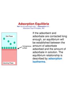
1 ENVE 204 Lecture -1 Review of pipe flow: Friction & Minor LossesAssist. Prof. Neslihan SEMERC Marmara UniversityDepartment of Environmental EngineeringAssist. Prof. Neslihan SemerciImportant DefinitionsAssist. Prof. Neslihan SemerciPressure pipe flow: Refers to full water flow in closed conduits of circular cross sections under a certain pressure a given discharge (Q), pipe flow at any location can be described by -the pipe cross section-the pipe elevation,-the pressure, and-the flow velocity in the pipe . Elevation (h)of a particular section in the pipe is usually measured with respect to a horizontal reference datum such as mean sea level (MSL). Pressure (P) in the pipe varies from one point to another, but a mean value is normally used at a given cross section. Mean velocity (V) is defined as the discharge (Q) divided by the cross-sectional area (A) Head Loss From pipe Friction Energy loss resulting from Friction in a pipeline is commonly termed the Friction head loss (hf) This is the head loss caused by pipe wall Friction and the viscous dissipation in flowing water.
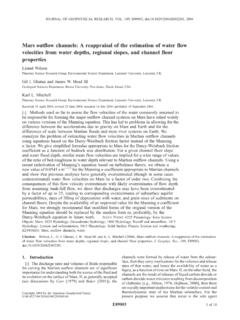
2 It is also called major loss .Assist. Prof. Neslihan SemerciFRICTION LOSS EQUATION The most popular pipe flow equation was derived by Henry darcy (1803 to 1858), JuliusWeiscbach(1806 to 1871), and the others about the middle of the nineteenth century. The equation takes the following form and is commonly known as the Prof. Neslihan SemerciTurbulent flow or laminar flow Reynolds Number (NR) < 2000 laminar flow Reynolds Number (NR) 4000 turbulent flow; the value of Friction factor (f) then becomes less dependent on the Reynolds Number but more dependent on the relative roughness (e/D) of the pipe . Assist. Prof. Neslihan SemerciRoughness Heigths, e, for certain common materialsAssist. Prof. Neslihan SemerciAssist. Prof. Neslihan SemerciFriction factor can be found in three ways:1. Graphical solution: Moody Diagram 2. Implicit equations : Colebrook-White Equation 3. Explicit equations: : Swamee-Jain EquationMoody DiagramAssist.
3 Prof. Neslihan SemerciDetermination of Friction Factor by using Moody Diagram (UseofMoodyDiagramtofindfrictionfactor): Acommercialsteelpipe, , ( ;turbulent-transitionalzone;turbulent-sm oothpipe;orturbulent-roughpipe)Assist. Prof. Neslihan SemerciUse of Moody Diagram Assist. Prof. Neslihan SemerciImplicit and explicit equations for Friction factor Colebrook-White Equation:1f= + Equation :f= ( + )2 Assist. Prof. Neslihan SemerciEmprical Equations for Friction Head Loss Hazen-Williams equation: It was developed for water flow in larger pipes (D 5 cm, approximately 2 in.) within a moderate range of water velocity (V 3 m/s, approximately 10 ft/s).Hazen-Williams equation, originally developed fort he British measurement system, has been writtten in the form = slope of the energy grade line, or the head loss per unit length of the pipe (S=hf/L).Rh= the hydraulic radius, defined as the water cross sectional area (A) divided by wetted perimeter (P).
4 For a circular pipe , with A= D2/4 and P= D, the hydraulic radius is = =D2/4 = 4 Assist. Prof. Neslihan SemerciEmprical Equations for Friction Head Loss Hazen-Williams equation: It was developed for water flow in larger pipes (D 5 cm, approximately 2 in.) within a moderate range of water velocity (V 3 m/s, approximately 10 ft/s).Hazen-Williams equation, originally developed fort he British measurement system, has been writtten in the form = British System = SI SystemS= slope of the energy grade line, or the head loss per unit length of the pipe (S=hf/L).Rh= the hydraulic radius, defined as the water cross sectional area (A) divided by wetted perimeter (P). For a circular pipe , with A= D2/4 and P= D, the hydraulic radius is = =D2/4 D= 4 Assist. Prof. Neslihan SemerciCHW= Hazen-Williams coefficient. The values of CHWfor commonly used water-carrying conduitsAssist. Prof. Neslihan SemerciEmprical Equations for Friction Head Loss Manning s Equation Manning equation has been used extensively open channel designs.
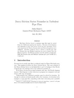
5 It is also quite commonly used for pipe flows . The Manning equation may be expressed in the following form: =1 2/3 1/2n= Manning s coefficient of roughness. In British units, the Manning equation is written as = 2/3 1/2where V is units of ft/s. Assist. Prof. Neslihan SemerciManning Rougness Coefficient for pipe -Assist. Prof. Neslihan SemerciMINOR LOSSL osses caused by fittings, bends, valves type of loss can be quantified using a loss coefficient (K). Losses are proportional to velocity of flow and geometry of device. Hm= loss coefficientAssist. Prof. Neslihan SemerciAssist. Prof. Neslihan Minor Loss at Sudden Contraction -Assist. Prof. Neslihan Minor Loss at Gradual ContractionAssist. Prof. Neslihan SemerciHead Loss at the entrance of a pipe from a large reservoirAssist. Prof. Neslihan Minor Loss in Sudden ExpansionsAssist. Prof. Neslihan Minor Loss in Gradual ExpansionsAssist.
6 Prof. Neslihan SemerciHead Loss due to a submerging pipe discharging into a large reservoirAssist. Prof. Neslihan SemerciKd = Loss in pipe valvesAssist. Prof. Neslihan SemerciMinor Loss in pipe BendsAssist. Prof. Neslihan Semerci