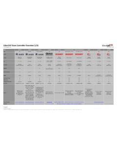
Transcription of EtherCAT Device Protocol Poster
1 EtherCAT Device ProtocolSpecification: < (4 digits)>Knowledge Base: Forum: dataTerminologyESMF rame processing and examplesDC unit and synchronizationSM and FMMUS laveOD AreaOD Index RangeCommunication index area0x1000 0x1 FFFRxPDO Mapping0x1600 0x17 FFTxPDO Mapping0x1A00 0x1 BFFRxPDO Assignment0x1C12 TxPDO Assignment0x1C13 Modules index area0x6000 0xAFFFI nput area0x6000 0x6 FFFO utput area0x7000 0x7 FFFD evice index area0xF000 0xFFFFSDO CommandSpecifierSDO Services0x02: SDO Request0x03: SDO Response0x08: SDO Info0x00 Download SegmentedUpload Segmented0x01 DownloadDownload SegmentedGet OD List OD List SegmentedDownloadGet Object Description TransferGet Object Description Entry Description Entry Description Info Error start addressLength Direction, Buffer *SM3*0x08000x08020x0804 Out, 1-buffer0x08080x080A0x080 CIn, 1-buffer0x08100x08120x0814 Out, 3-buffer0x08180x081A0x081 CIn, 3-bufferValueData TypeValueData TypeValueData TypeValueData Type0x0001 BOOL/BIT0x0006 UINT0x000 BARRAY of UINT0x001 FWORD0x0002 SINT0x0007 UDINT0x0011 LREAL0x0020 DWORD0x0003 INT0x0008 REAL0x0015 LINT0x0260 ARRAY of INT0x0004 DINT0x0009 STRING(n)
2 0x001 BULINT0x0261 ARRAY of SINT0x0005 USINT0x000 AARRAY of BYTE0x001 EBYTE0x0262 ARRAY of DINTO bject DictionaryModule 0 Module nCommunication area (0x1000 0x1 FFF) object 0x1000, 0x1018, 0x10F3 RxPDOs (0x1600 0x17FF) (0x1A00 0x1 BFF) specific area (0x2000 0x5 FFF)Input area (0x6000 0x6 FFF)0x6000 0x600F 0x6010 0x601F ..0x6nn0 0x6nnFTx-mappable, read-onlyOutput area (0x7000 0x7 FFF)0x7000 0x700F0x7010 0x7nnFRx-mappable, read-writeableConfiguration area (0x8000 0x8 FFF)0x8000 0x800F0x8010 0x8nnFread-writeable, usually not mappableInformation area (0x9000 0x9 FFF)0x9000 0x900F0x9010 0x9nnFread-only, usually not mappableDiagnosis area (0xA000 0xAFFF)0xA000 0xA00F0xA010 0xAnnFDevice area (0xF000 0xFFFF)
3 Object 0xF000, 0xF010, 0xF030, 0xF050 SpecifierCmdDescription0x00 NOPNo operation0x01 APRDAuto increment physical read0x02 APWRAuto increment physical write0x03 APRWAuto increment physical read write0x04 FPRDC onfigured address physical read0x05 FPWRC onfigured address physical write0x06 FPRWC onfigured address physical read write0x07 BRDB roadcast read0x08 BWRB roadcast write0x09 BRWB roadcast read write0x0 ALRDL ogical memory read0x0 BLWRL ogical memory write0x0 CLRWL ogical memory read write0x0 DARMWAuto increment physical read multiple write0x0 EFRMWC onfigured address physical read multiple writeCommandActionIncrementxRDSuccessful read+1xWRSuccessful write+1xRWSuccessful readSuccessful
4 Write+1+2 Info (128 Bytes)ESC ConfigurationConfigured Station AliasCRCI dentityVendor IDProduct CodeRevision NumberSerial NumberHardware DelaysBootstrap MBX SM ConfigurationStandard MBX SM Controlreg0x0100 0x0103DL Statusreg0x0110 0x0111 Frame Error Counterreg0x0300reg0x0302reg0x0304reg0x0 306 Phys. Error Counterreg0x0301reg0x0303reg0x0305reg0x0 307 Link Lost Counterreg0x0310reg0x0311reg0x0312reg0x0 313 EtherCAT State Machine (ESM)The EtherCAT State Machine defines a step-by-step set-up of each individual EtherCAT slave Device and indicates available functionalities. A Device can re-ject a state request from the master and signal an error with an error indica-tion (error flag in AL Status register) and a related error code (AL Status Code register).
5 The state request, state response and error response is exchanged via the ESC AL Control register (reg0x0120), AL Status register (reg0x0130) and AL Status Code register (reg0x0134). The ESM specifies the slave behavior, while the master adopts it respectively. The ESM description below outlines the basic actions for each state transition: commands sent by the master and (local) behavior of the connected data configurationThe EtherCAT process data configuration allows very flexible PDO description. PDO configuration can be either fixed, selectable or configurable. When using MDP objects, inputs(obj0x6000 0x6 FFF) and outputs (obj0x7000 0x7 FFF) are mapped to PDO mapping objects (obj0x1600 0x16FF for RxPDO mapping and obj0x1A00 0x1 BFF for TxPDO mapping ) and assigned to the respective SM via obj0x1C12 (SM2) and obj0x1C13 (SM3) for PDO Assignment.
6 PDO mapping and PDO Assignment objects are used by complex devices (with online and offline OD) as well as by simple devices (only in the EtherCAT Slave Information file).Communication principleEtherCAT communication is always initiated by the master by sending frames via its Ethernet interface. Those are processed on the fly by the ESC. Processing within the ESC works in a roundabout fashion: Behind the EtherCAT Processing Unit (EPU) the frame is forwarded to the next port (and, if open, sent out to be processed by other slaves), while the returning frame is sent back to the master via port 0. Port 0 shall always be the IN port of the slave Device . The topology always forms a logical ring, and neither frame collision nor congestion can occur by design.
7 Throughput time can be calculated precisely, and errors can be detected easily via status and error counter registers (reg0x0100, reg0x0300 0x0313).Reference: Frame processing principlesMasterRxPDO Assigmentobj0x1C12 RxPDO Mappingobj0x1600 Assigmentobj0x1C13 TxPDO Mappingobj0x1A00 structure and EtherCAT Slave Controller (ESC)The ESC processes the EtherCAT frames on the fly in hardware and implements the functionalities of the data link layer (DLL). Those include SyncManagers (SM), Fieldbus Memory Management Units (FMMU) and DC unit. Typically, EtherCAT slaves implement the application layer (AL) functionalities such as the ESM, parameter handling and process data handling on a C such slaves are called complex Device .
8 Only for very simple I/O devices without parameters and without necessary AL error handling, the I/O hardware drivers are connected directly to the digital I/O interface of the ESC such slaves are called simple Device .The block diagram combines elements of the slave s hardware structure, functional entities of the ESC, software structure and Protocol Device Profile (MDP)The MDP provides a basic structure for any EtherCAT slave to organize physical or logicalmodules within the Device , based on the CoE OD. The slave s data is grouped based on its physical structure and/or logical/software structure. The MDP structure is based on so-called modules. A module has an assigned index range, typically: 1 RxPDO, 1 TxPDO (PdoIncrement = 1) 16 objects (with up to 255 entries per object) per functional index area (inputs, outputs, configuration, information, diagnosis) (IndexIncrement = 16).
9 Information which is not specific for a module is organized in the 0xFxxx Device index Object Dictionary structure, incl. MDP structureGeneral OD structure, MDP structure (0x6000 ff.) and attributes of the functional index areas:Reference: MDP Device modelMDP DeviceProfilesThe major part of profiles is based on the CoE OD (incl. range 0x6000 ff.), while there are MDP- based profiles and the IEC61800 drive profiles (incl. DS402 ). The 32-bit profile number is pro-vided by the slave via Obj0x1000, Obj0xF010 and via ESI element Device :Profile or Module:Profile. Bit 0-15 is the Device profile number ( 5003 for Semi Device Profile). Bit 16-31 is the module profile number ( 2020 mass Flow Controller).
10 Important profiles are: General MDP Device Model Specification: Basic structure for any EtherCAT slave MDP Fieldbus Gateway Profile Specification: Incl. profiles for EtherCAT masters, Profibus DP, CAN, CANopen, DeviceNet MDP Safety Module Specification: Incl. profiles for FSoE Digital I/O connection, FSoE Safety Drive Profile, FSoE Master Semi Device Profile: Based on MDP structures, incl. profiles for mass flow controllers, temperature controllers, pressure gauges, valves, chillers, pumps, RF DC generators Implementation Directive for CiA402 Drive Profile (IEC61800-7-201)Distributed Clocks (DC) and synchronizationSynchronization of master and slave applications is based on a common time in the network (DC System Time).
