Transcription of Examples - structuremag.org
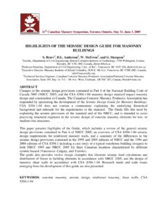
1 STRUCTURE magazineMay 2008discussions on design issues for structural engineersStructural DeSignMay 2008 STRUCTURE magazineINTERIORINTERIOREXTERIOREXTERIOR INTERIOR PILASTEREXTERIOR PILASTERF igure Tall masonry WallsDavid T. Biggs, you ever designed a bearing wall 20 feet high? How about 25 feet or 35 feet or even 50 feet? Have you ever considered the feasibility of a 50-foot tall bearing wall?There are many options available to engineers who would like to design tall masonry walls. As a result of miscon-ceptions, misunderstandings, or lack of knowledge, masonry is not being used to its full capacity to build tall walls. Let s look at ways to design really tall single-story exterior walls. Historical PerspectiveFor years, engineers have relied upon empirical design criteria for determin-ing maximum wall heights and their associated thicknesses.
2 The criteria known as h/t limitations (height to thickness) was developed based upon historical data of unreinforced ma-sonry. There is little rational analysis to justify h/t values. The strength of the masonry and the mortar type used in the construction are not included in these limitations. However, a stress cal-culation for compression based upon gross section properties is empirical criteria in the 2005 edition of the Building Code Requirements for masonry Structures (ACI 530/ASCE 5/TMS 402) developed by the masonry Standards Joint Committee (MSJC), exterior walls are limited to an h/t (height to thickness) of 20 for solid or fully grouted bearing walls, and an h/t of 18 for all other exterior walls (non-loading bearing walls or bearing walls not solid or fully grouted).
3 The heights of exterior walls are therefore limited as noted in Table values have been in various masonry standards for years, and they are often misused by many architects and engineers for all walls. That s the mistake! These criteria do not apply to engineered masonry . Whether you design unreinforced or reinforced ma-sonry walls, these height limitations can be exceeded if the walls are engi-neered using criteria from the MSJC. Let s review some of the options!Current design OptionsEngineered Unreinforced masonry using Allowable Stress design (ASD)The height of an unrein-forced masonry wall that is engineered is governed by design stresses and buckling capacity. For a loadbearing wall designed in accordance with the Allowable Stress design methodology, an engineer must design the wall so as not to exceed the allowable stresses for the masonry and the mortar.
4 There is no absolute h/t limit!For loadbearing walls, there is also a buckling capacity check that could restrict the actual height of the walls. The buckling capacity is reduced for slenderness effects based upon the h/r ratio (height to radius of gyration). The radius of gyration is approximately 30 percent of the thickness t. While there is no absolute maximum height limit, the maximum h/t is effectively limited based upon the loads applied. Building really tall with this method requires very thick walls. Possible? Yes. Practical? Maybe not!Engineered Reinforced masonry using Allowable Stress DesignReinforced masonry designed using Allowable Stress design follows similar guidelines as that used for unreinforced masonry in that there is no maximum height limit.
5 The maximum wall height is controlled by the loadings and slen-derness effects. The slenderness effects are based upon the h/r ratio and pre-vent the wall from single-wythe walls, allowable stress methods generally do not allow really tall walls to be designed without building thick. We ll see later how reinforced methods can be used to go Reinforced masonry using Strength DesignOne efficient method for designing tall walls uses Strength design methods. Since 1985, strength methods have been codified, starting first with the Uniform Building Code and now embodied within the MSJC and the International Building Code (IBC).This method has no specific limit on h/t. However, it has design criteria that limit service load deflections and ultimate moment capacity for out-of-plane loads.
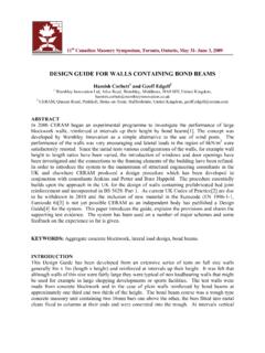
6 The service load deflections cannot exceed percent of the wall WallsLimiting HeightBearing WallsSolid brick or fully grouted CMU 8 inch13 -4 10 inch16 -8 12 inch20 -0 Hollow or partially grouted CMU 8 inch12 -0 10 inch15 -0 12 inch18 -0 Non-bearings Walls 8 inch12 -0 10 inch15 -0 12 inch18 -0 Table 1: Empirical Limitations18S T R U C T U R E magazineCopyrightS T R U C T U R E magazineCopyrightMay 2008 STRUCTURE magazineMay 2008 CLe = 2 DEAD LOAD - 750 plfLIVE LOAD = 1,200 plfW = 25 psfVERTICAL TABLE CELLS WITHREINFORCEMENT8 CMUhSECTIONF igure For a 30-foot wall, that s inches over 30 feet for a simply supported create really tall walls, there is an axial load capacity limitation when the h/t ex-ceeds 30. The factored axial load for these walls must be limited to 5 percent of the f m based upon the gross section properties.
7 The minimum wall thickness is 6 inches also. It is not uncommon to create designs with an h/t from 32 to 50. That could produce wall heights of up to 33 feet for walls built with 8-inch concrete masonry units (CMU), 41 feet for 10-inch CMU, and 50 feet for 12-inch CMU. Regionally, 14- and 16-inch CMU are available, which extend possible wall heights even engineers may choose to avoid this method because they are not familiar with it. However, there are code standards from MSJC and several excellent references that explain the method, and there is computer software that makes it relatively easy to create design options. (The online version of this article, , contains specific references.)PilastersAnother method to build tall uses pilasters built with the walls.
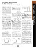
8 The pilasters are stiffening elements. Figure 1 shows two options for pilasters. They can be either interior or exterior to the advantages of using pilasters include:a) The wall sections between the pilasters are only as thick as is needed to span horizontally between the ) The system works well with the Allowable Stress design method, a process many engineers are familiar disadvantage is that interior pilasters decrease the usable space within the building because of the thickened wall section. Another is that the loadings to the top of the exterior pilaster are normally eccentric to the pilaster and reduce the load height of the wall is governed by the size of the pilaster and its load WallsThis wall system is not commonly used in the United States, but provides almost unlimited height possibilities.
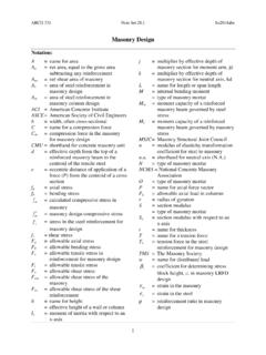
9 The walls are basically two wythes joined by cross walls (diaphragm walls) that interlock the two wythes and create a composite wall of variable thickness. The spacing of the cross walls should be less than 6 times the thickness of the wythes. The two wythes are conventionally reinforced by partially or fully grouting the cores. (Figure 2)t wallt wytheCROSS WALLSPACING < 6t wytheREINFORCEMENTSPACINGREINFORCEDWYTHE SVOIDCROSS WALLF igure you for reviewing this ad proof for the upcoming issue of STRUCTURE ensure that the proper advertisement for your company is run, please print out this document, fi ll out the information below and fax it to us at: , the ad looks fi , we require the following changes:If we recieve no fax within 48 hours of this email, we will assume that there is no change necessary and will run the ad as presented here.
10 Thank you for your 111/28/2007 10:31:37 AM ADVERTISEMENT For Advertiser Information, visit on next pageS T R U C T U R E magazineCopyrightS T R U C T U R E magazineCopyrightSTRUCTURE magazineMay 2008 STRUCTURE magazineMay 2008 STRUCTURE magazine20 CLe = 2 DEAD LOAD - 750 plfLIVE LOAD = 1,200 plfW = 25 psfhSECTIONCAP BEAM8 CMUCROSSWALLSVOID6 CMUWYTHESX-X2 - 8 ON CENTERXX2 -0 DIAPHRAGMWALLVERTICALREINFORCEMENTAS REQUIREDF igure used. The axial loads and lateral loads are the same for each example. The maxi-mum wall heights for each option are cal-culated. It may be intuitive, but the more sophisticated the design technique, the taller the walls can 3 (page 19) shows the same single-wythe, 8-inch bearing wall designed by Empirical, ASD, and Strength methods.