Transcription of EXHAUST AND AIR LOUVERS - TECHNOFAB ENG
1 CHAPTER 5 EXHAUST AND AIR LOUVERSEXHAUST AND AIR LOUVERS3 EXHAUST AND AIR LOUVERSThe Aluminium EXHAUST and Fresh Air LOUVERS of TFE are used both internally and externally in buildings for the extraction of re - cycled air, intake of external fresh air of the expulsion of contaminated air. The quality of the material used and the particular inclination of the blades at 60 angle downward offer a weather resistant LOUVERS which Construction: Frame & Blades are made of high quality Extruded Aluminium Profiles of 6063 Alloy. Frame Flange width: 30 mm. Blades: Fixed Louverd type arranged horizontally and inclined downward to 60 degree angle in order to:- prevent the ingress of rain Prevent the ingress of Block vision while straight Be suitable for external walls and screening applications.
2 The blades are positioned on 25 mm minimum centers up to 35 mm maximum centers resulting in a high free area to provide minimum resistance to air flow. Available in wide variety of neck sizes with 1 00 x 1 00 mm minimum single section size and 2 mtr maximum single section height. LOUVERS height exceeding 2 mtr to be fabricated and supplied in multiple sections depending on length and height dimensions as well as site conditions. The assembly of multiple sections is unlimited, where gives good protection against the direct ingress of rain water, leaves and birds. Can also be used directly installed on walls for the ventilation of industrial areas.
3 Also suitable for the use with an adjustable or overpressure damper for air flow and pressure Notes:01 Introduction,Features & Models, EXHAUST Air Models,Fresh Air Profiles used In EXHAUST & Fresh Air LOUVERS , AvaUable Effective Area Values for EXHAUST and Fresh Air Tabular Selection for EXHAUST and Fresh Air Louvers07 Air Flow Resistance Diagram, Selection Ordering & Characteristics: each section operates independently. Multiple sections: Supplied as separate sections and assembly by others on site. The Fresh Air Louver is suitable for the use in air inlet of fresh air ducts and air handling units.
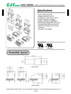
4 It s also suitable for the use at dirty air EXHAUST discharge. Wire Mesh screen of galvanized steel is attached to the interior face of the louver as an option, mesh size 3 x 3 mm. EXHAUST Air LOUVERS are available with different type of attachments such as:-Opposed Blade Damper (Model EAL +D).- Aluminium Filter (Model FAL c/w Filter).- Both the Damper and Filter (Model FAL + D c/w Filter). Available with Foam type Rubber Gasket for air sealing (provided as an option). Mounting instructions: see page No. EL-04 Surface Finishes: see page No. AND AIR LOUVERS54 EXHAUST Air LouversConstruction and Dimensional DetailsN : Nominal/Listed Size = Length (L) x Height (H)A : ActualSize =(L-10) x(H-10) F : Face Size = (l+50) X (H+50) N : Nominal/Listed Size = Length (L) x Height (H)A : Actual Size = (L-10) x (H-10)F :Face Size = (L+50) x (H+50)Model EALM odel EAL Model EAL + D (Double Frame)Model FAL + D c/w Filter (Double Frame) EXHAUST Air LOUVERS furnished approximately 10 mm less than the NominaVListed Size.
5 AllDimensions are in mm and subject to:t1 mm tolerance EXHAUST Air LOUVERS furnished approximately 10 mm less than the NominaVListed Size. AllDimensions are in mm and subject to:t1 mm tolerance Wire Mesh (optional). Filter : Aluminium Washable Filter Media of 1 /2 standard thickn ss 11 & 2 thicknesses also available on request as an option. Wire Mesh (optinal). For Opposed Blade Damper details and construction refer to chapter (1) or (2). Filter : Aluminium Washable Filter Media of 1/2 standard thickness (1 & 2 thicknesses also available on request as an option). Double Frame LOUVERS are provided with door hinge from one side and screw from other side allowing the second frame (inner one) to act as an access door to the Filter and I or Opposed Blade Damper.
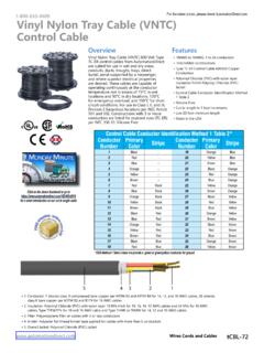
6 EXHAUST Air LOUVERS furnished approximately 1 0 mm less than the Nominal/Listed Size. All Dimensions are in mm and subject to 1 mm AND AIR LOUVERS76 L & H Dimensions are in mm. Damper at full open position (if any). All Dimensions are in mm and subject to mm Fixing MountingCross Sectional Drawings for Profiles used in EXHAUST and Fresh Air LouversEFFECTIVE AREA VALUES FOR EXHUAST AND FRESH AIR LOUVERS IN (m2) Engineering and Performance DataA. Concealed Fixing (Spring Clip Mounting)The Louver is fixed by means of spring clips to the wall or partition where no screws ore Face Screw FixingThe Louver is fixed to the wooden frame by means of visible AND AIR LOUVERS98easel:Illustrative Example :Given Data : Required Model : EALAir Flow Rate : 650 CFM [307 LIS) Assume V f.]
7 Not exceeding m/s [300 FPM).Refer to page No. EL-06 Table EL-03.@ 650 CFM andV f. = m/s to read the related data as below :Pressure Drop = Po ( ) A elf. = m2By applying the A elf. value to table No. EL-01,simply you can select the size of 700 x 500 mm which is having the nearest area value to the required :Illustrative Example :Given Data : Required Model : FAL c/W FilterAir Flow Rate : 3500 CFM (1652 L/S) Assume V f. not exceeding m/s [300 FPM).Since the CFM given is out of the range of Table divide the ( 3500 ) by [2) to give 1750 CFM and read the related data at this value as below : Pressure Drop = Po [ lnwg)Aeff.]]]]
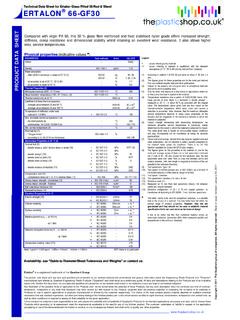
8 = m2By applying the A elf. value to table , simply you can select the size of 950 x 900 mm which is having the nearest area value to the required obtain the required 3500 CFM -double the area while maintaining the same height asbelow : (l X 2) X (H) = (950 X 2) X (900) mmFinalsize= 1900 x 900 ProcedureAir Flow Resistance Diagram (All Models) Pressure Drop (t:. Pt) versus Face Velocity (Vf)Ordering DataAvailable Surface Finishes For EXHAUST And Fresh Air LOUVERS :Available Surface Finishes For Opposed Blade Damper:Specify: Natural I Matt Silver Anodized. Powder Coating (Standard Colors are white RAL 9010 I 9016.)
9 Other optional colors if required to be provided in RAL- and charged extra). Aluminium in Mill Finish (standard).1. Louver Description I Model ( EXHAUST or Fresh, with orwlo Opposed Blade Damper).2. Wire Mesh (only mention if required).3. Nominal / Neck Size4. EXHAUST I Fresh Air LOUVERS Surface Finish. Aluminium in Mill Finish. Other Special finishes (on request if available). Matt Black Powder Coating (optional).6. RAL- No. (Only mention if powder coating surface finish is required).7. Type of Fixing {Concealed or Face Screw Fixing).8. Thickness of Aluminium Filter for Fresh Air LOUVERS (only mention if optional 1 or 2 thickness is required).}
10 9. Rubber Gasket {only mention if required).10. Remarks if 1:Example 2:Example 3:Gravity LOUVERS GL and Non Return Dampers11 Gravity LOUVERS GL and Non Return Dampers Gravity LOUVERS GL and Non Return Dampers NRD are generally used in intake and discharge applications in residential, commercial and industrial ventilated systems. GL s and NRD s guarantee that the automatic opening of the blades will occur when the fan or system is switched on and equally will close when switched off in order to avoid passage of air when the system is closed, preventing the reverse of air flow. They are also used to maintain certain pressure in pressurized treated areas with respect to others, thus only when pressure is exceeding the designed Gravity LOUVERS (GL): Frame construction: made of high quality Extruded Aluminium Profiles of 6063 Alloy.}